INSTALLATION
Removal / installation · Vehicles built Sep 2011 – Dec 2011
| 1. INSTALL EXHAUST MANIFOLD SUB-ASSEMBLY LH |

Place a new gasket on the cylinder head with the "L" mark facing the manifold side.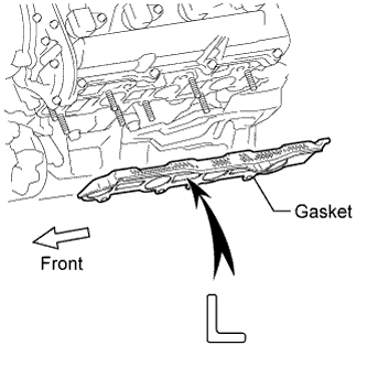

- NOTICE:
- Be careful of the installation direction.
Temporarily install the exhaust manifold with 8 new nuts, and then uniformly tighten the nuts in several steps, in the sequence shown in the illustration.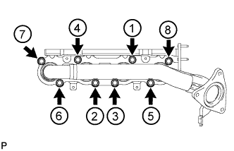
- Torque:
- 44 N*m{ 449 kgf*cm , 32 ft.*lbf }
| 2. INSTALL NO. 2 EXHAUST MANIFOLD HEAT INSULATOR |
Temporarily install the heat insulator with the 4 bolts.
Uniformly tighten the 4 bolts in several steps, in the sequence shown in the illustration.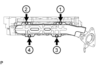
- Torque:
- 7.5 N*m{ 76 kgf*cm , 66 in.*lbf }
| 3. INSTALL NO. 2 MANIFOLD STAY |
Install the manifold stay with the 3 bolts.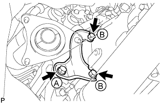
- Torque:
- for bolt A:
- 36 N*m{ 367 kgf*cm , 27 ft.*lbf }
- for bolt B:
- 71 N*m{ 724 kgf*cm , 52 ft.*lbf }
| 4. INSTALL EXHAUST MANIFOLD SUB-ASSEMBLY RH |
Place a new gasket on the cylinder head with the "R" mark facing the manifold side.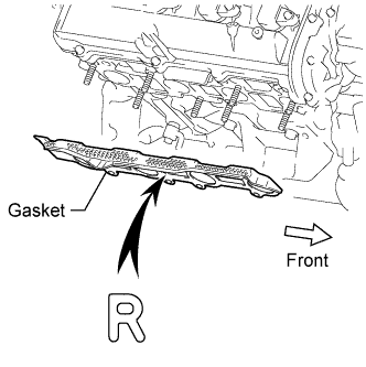
- NOTICE:
- Be careful of the installation direction.
Temporarily install the exhaust manifold with 8 new nuts, and then uniformly tighten the nuts in several steps, in the sequence shown in the illustration.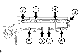
- Torque:
- 44 N*m{ 429 kgf*cm , 32 ft.*lbf }
| 5. INSTALL NO. 1 EXHAUST MANIFOLD HEAT INSULATOR |
Temporarily install the heat insulator with the 4 bolts.
Uniformly tighten the 4 bolts in several steps, in the sequence shown in the illustration.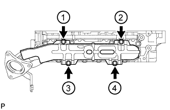
- Torque:
- 7.5 N*m{ 76 kgf*cm , 66 in.*lbf }
| 6. INSTALL NO. 1 MANIFOLD STAY |
Install the manifold stay with the 3 bolts.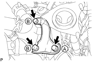
- Torque:
- for bolt A:
- 36 N*m{ 367 kgf*cm , 27 ft.*lbf }
- for bolt B:
- 71 N*m{ 724 kgf*cm , 52 ft.*lbf }
| 7. CONNECT TRANSMISSION OIL COOLER ASSEMBLY (w/o Air Cooled Transmission Oil Cooler) |
Connect the transmission oil cooler with the 2 bolts.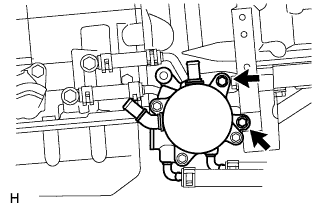
- Torque:
- 21 N*m{ 214 kgf*cm , 15 ft.*lbf }
Connect the 2 water bypass hoses to the transmission oil cooler.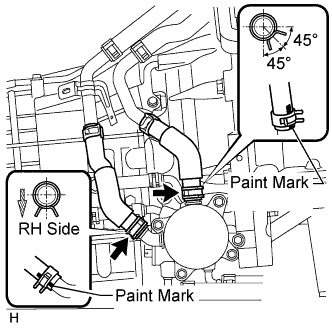
- NOTICE:
- Make sure the pinching portion of each clip is facing the direction shown in the illustration.
Install the hose heat protector with the bolt.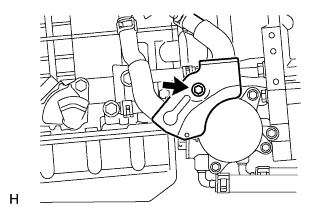
- Torque:
- 21 N*m{ 214 kgf*cm , 15 ft.*lbf }
| 8. INSTALL FRONT NO. 2 EXHAUST PIPE ASSEMBLY |
Install a new gasket and the front No. 2 exhaust pipe to the exhaust manifold LH with 3 new nuts.
- Torque:
- 54 N*m{ 554 kgf*cm , 40 ft.*lbf }
Connect the air fuel ratio sensor connector.
Connect the heated oxygen sensor connector.
| 9. INSTALL FRONT EXHAUST PIPE ASSEMBLY |
Install a new gasket and the front exhaust pipe to the exhaust manifold with 3 new nuts.
- Torque:
- 54 N*m{ 554 kgf*cm , 40 ft.*lbf }
Connect the air fuel ratio sensor connector.
Connect the heated oxygen sensor connector.
Attach the heated oxygen sensor wire clamp.
| 10. INSTALL CENTER EXHAUST PIPE ASSEMBLY |
Install the center exhaust pipe to the 3 exhaust pipe supports.
Install 2 new gaskets to the front exhaust pipe and front No. 2 exhaust pipe.
Install the 4 bolts.
- Torque:
- 48 N*m{ 489 kgf*cm , 35 ft.*lbf }
| 11. INSTALL TAILPIPE ASSEMBLY |
Install the tailpipe to the 2 exhaust pipe supports.
Install a new gasket to the center exhaust pipe.
Connect the tailpipe and center exhaust pipe with a new clamp.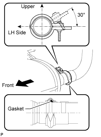
- Torque:
- 32 N*m{ 326 kgf*cm , 24 ft.*lbf }
- HINT:
- Install the clamp within the angle range shown in the illustration.
| 12. INSTALL NO. 2 ENGINE UNDER COVER |
Install the No. 2 engine under cover with the 2 bolts.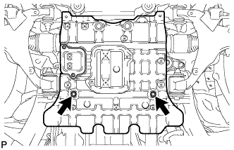
- Torque:
- 29 N*m{ 296 kgf*cm , 21 ft.*lbf }
| 13. INSTALL ENGINE OIL LEVEL DIPSTICK GUIDE |
Apply a light coat of engine oil to a new O-ring.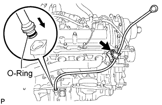
Install a new O-ring to the guide.
Install the dipstick guide with the bolt.
- Torque:
- 8.0 N*m{ 82 kgf*cm , 71 in.*lbf }
Install the dipstick.
| 14. CONNECT COOLER COMPRESSOR |
Connect the compressor. Then install it and the No. 1 compressor stay with the nut and 3 bolts.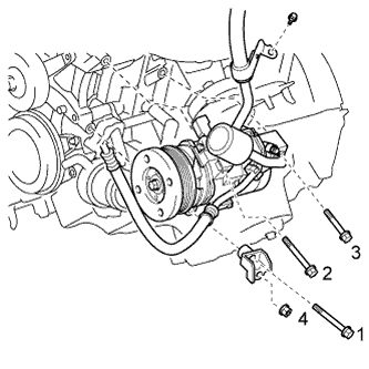
- Torque:
- for bolt:
- 45 N*m{ 459 kgf*cm , 33 ft.*lbf }
- for nut:
- 25 N*m{ 250 kgf*cm , 18 ft.*lbf }
- HINT:
- Tighten the bolts in the order shown in the illustration to install the cooler compressor.
Install the cooler refrigerant suction hose with the bolt.
- Torque:
- 9.8 N*m{ 100 kgf*cm , 87 in.*lbf }
Connect the connector.
| 15. INSTALL AIR TUBE SUB-ASSEMBLY RH |
Install a new gasket and connect the air tube to the exhaust manifold with the 2 nuts.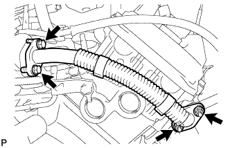
- Torque:
- 10 N*m{ 102 kgf*cm , 7 ft.*lbf }
Install a new gasket and connect the air tube to the No. 1 air switching valve with the 2 bolts.
- Torque:
- 10 N*m{ 102 kgf*cm , 7 ft.*lbf }
| 16. INSTALL NO. 3 AIR TUBE |
Install a new gasket and connect the No. 3 air tube to the exhaust manifold with the 2 nuts.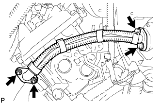
- Torque:
- 10 N*m{ 102 kgf*cm , 7 ft.*lbf }
Install a new gasket and connect the No. 3 air tube to the No. 2 air switching valve with the 2 bolts.
- Torque:
- 10 N*m{ 102 kgf*cm , 7 ft.*lbf }
| 17. CONNECT NO. 1 WATER BY-PASS PIPE (w/o Air Cooled Transmission Oil Cooler) |
Connect the water by-pass pipe to the cylinder head cover RH with the 2 bolts.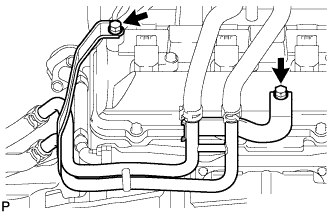
- Torque:
- 18 N*m{ 184 kgf*cm , 13 ft.*lbf }
| 18. INSTALL INTAKE MANIFOLD |
Install the intake manifold (Click here).
| 19. INSPECT FOR EXHAUST GAS LEAK |
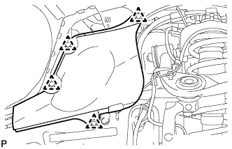
| 20. INSTALL FRONT FENDER APRON SEAL LH |
Install the fender apron seal with the 4 clips.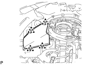
| 21. INSTALL FRONT FENDER APRON SEAL LH (w/ KDSS) |
Install the fender apron seal with the 3 clips.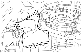
| 22. INSTALL FRONT FENDER APRON SEAL REAR LH |
Install the fender apron seal with the 4 clips.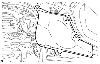
| 23. INSTALL FRONT FENDER APRON SEAL FRONT RH |
Install the fender apron seal with the 3 clips.
| 24. INSTALL FRONT FENDER APRON SEAL REAR RH |
Install the fender apron seal with the 4 clips.