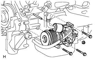
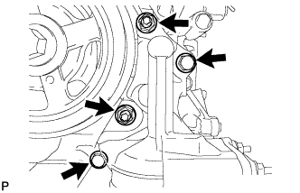
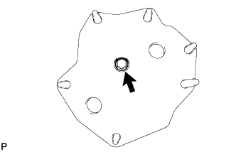
Remove the 3 bolts, nut and stud bolt, and then disconnect the cooler compressor.
HINT:
It is not necessary to completely remove the compressor. With the hoses connected to the compressor, hang the compressor on the vehicle body with a rope.
3.
DRAIN ENGINE OIL
Remove the oil filler cap.
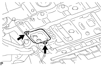
Remove the 2 bolts and No. 2 engine under cover seal.
Remove the oil pan drain plug and gasket, and drain the engine oil into a container.
Install a new gasket and the oil pan drain plug.
Torque:
40 N*m{
408 kgf*cm
, 30 ft.*lbf
}
Install the No. 2 engine under cover seal with the 2 bolts.
Torque:
10 N*m{
102 kgf*cm
, 7 ft.*lbf
}
4.
REMOVE OIL FILTER ELEMENT
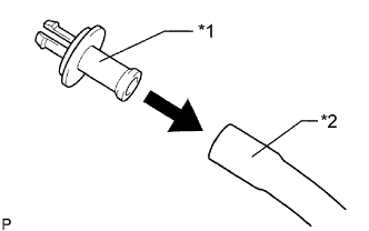
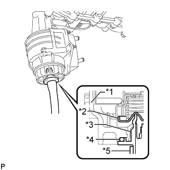
Connect a hose with an inside diameter of 15 mm (0.591 in.) to the pipe.
Text in Illustration
*1
Pipe
*2
Hose
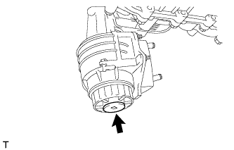
Remove the oil filter drain plug.
Install the pipe to the oil filter cap.
Text in Illustration
*1
Cap
*2
Valve
*3
Pipe
*4
O-Ring
*5
Hose
NOTICE:
If the O-ring is removed with the drain plug, install the O-ring together with the pipe.
HINT:
Use a container to catch the draining oil.
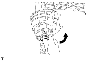
Check that oil is drained from the oil filter. Then disconnect the pipe and remove the O-ring as shown in the illustration.
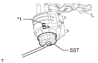
Using SST, remove the oil filter cap.
SST
09228-06501
Text in Illustration
*1
Oil Filter Bracket Clip
NOTICE:
Do not remove the oil filter bracket clip.
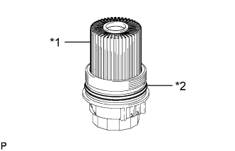
Remove the oil filter element and O-ring from the oil filter cap.
Text in Illustration
*1
Oil Filter Element
*2
O-Ring
NOTICE:
Be sure to remove the cap O-ring by hand, without using any tools, to prevent damage to the cap O-ring groove.
5.
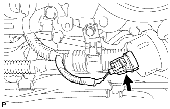
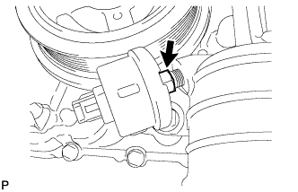
REMOVE OIL PRESSURE SENDER GAUGE ASSEMBLY
Disconnect the oil pressure sender gauge connector.
Remove the oil pressure sender gauge.
6.
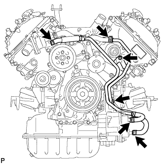
REMOVE NO. 2 WATER BY-PASS PIPE SUB-ASSEMBLY
Remove the 2 bolts.
Disconnect the 4 hoses and remove the No. 2 water by-pass pipe.
7.
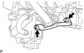
REMOVE NO. 1 OIL COOLER BRACKET
Remove the 2 nuts and bracket.
Disconnect the ground wire from the cylinder block.
8.
REMOVE OIL FILTER BRACKET
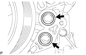
Remove the 2 bolts, 2 nuts and filter bracket.
Remove the 2 O-rings.
9.
REMOVE OIL COOLER ASSEMBLY
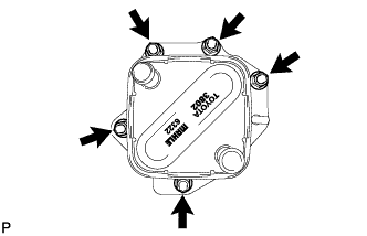
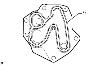
Remove the 5 nuts and oil cooler from the oil filter bracket.
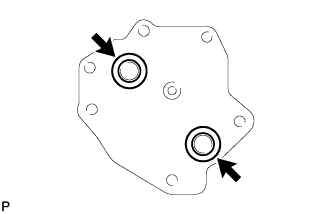
Remove the 2 O-rings.
10.
REMOVE OIL COOLER SPACER
Remove the bolt and oil cooler spacer from the oil filter bracket.