ON-VEHICLE INSPECTION
Inspection · Vehicles built from Sep 2011
| REMOVE V-BANK COVER SUB-ASSEMBLY |

Raise the front of the V-bank cover to detach the 3 pins. Then remove the 2 V-bank cover hooks from the bracket, and remove the V-bank cover.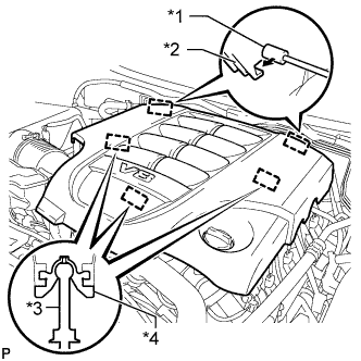

Text in Illustration *1
Bracket
*2
Hook
*3
Pin
*4
Grommet
| INSPECT VACUUM SWITCHING VALVE ASSEMBLY (for ACIS) |
Disconnect the vacuum switching valve connector.
Measure the resistance according to the value(s) in the table below.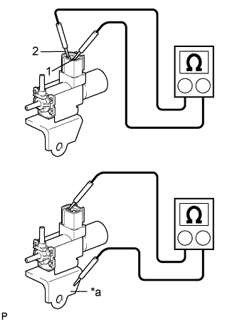
Text in Illustration *a
Body Ground
- Standard Resistance:
Tester Connection
Condition
Specified Condition
1 - 2
20°C (68°F)
37 to 44 Ω
1 - Body ground
Always
1 MΩ or higher
2 - Body ground
When applying vacuum to port E, check that air is sucked into the filter.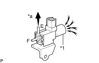
If the result is not as specified, replace the vacuum switching valve assembly.Text in Illustration *1
Filter
*a
Vacuum
Apply battery voltage to the connector, and check the VSV operation.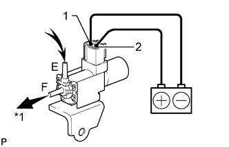
- OK:
Measurement Condition
Specified Condition
Battery positive (+) → Terminal 1
Battery negative (-) → Terminal 2
Air is sucked into port E when a vacuum is applied to port F
If the result is not as specified, replace the vacuum switching valve assembly.Text in Illustration *a
Vacuum
Connect the vacuum switching valve connector.
| INSTALL V-BANK COVER SUB-ASSEMBLY |
Attach the 2 V-bank cover hooks to the bracket. Then align the 3 V-bank cover grommets with the 3 pins, and press down on the V-bank cover to attach the pins.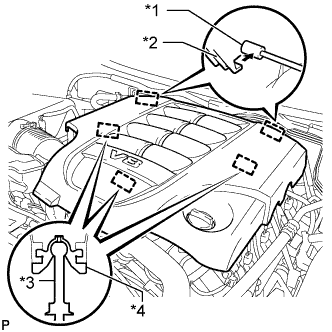
Text in Illustration *1
Bracket
*2
Hook
*3
Pin
*4
Grommet