REMOVAL
Removal / installation · Vehicles built from Sep 2011
| 1. REMOVE SPARE WHEEL CARRIER HINGE BRACKET (w/ Tire Carrier) |

Detach the 2 claws and remove the spare wheel carrier hinge bracket.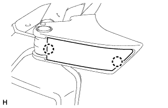

| 2. REMOVE SPARE WHEEL COVER SUB-ASSEMBLY (w/ Tire Carrier) |
Remove the 2 nuts.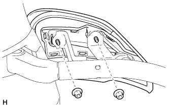
Detach the clip and remove the spare wheel cover.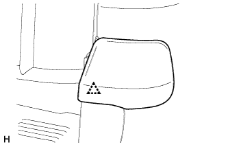
| 3. REMOVE SPARE WHEEL CARRIER SUB-ASSEMBLY (w/ Tire Carrier) |
Remove the 3 bolts and spare tire.
Remove the 9 bolts and spare wheel carrier.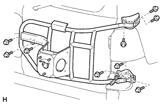
| 4. REMOVE PINTLE HOOK ASSEMBLY (w/ Pintle Hook) |
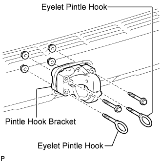 |
For vehicles with a spare tire installed to the underbody, remove the spare tire.
Remove the 4 nuts.
Remove the 2 bolts, 2 eyelet pintle hooks, pintle hook assembly and pintle hook bracket.
| 5. REMOVE REAR QUARTER PANEL MUDGUARD LH |
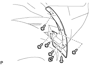 |
Remove the clip.
Using a T30 "TORX" socket, remove the 6 screws and mudguard.
| 6. REMOVE REAR QUARTER PANEL MUDGUARD RH |
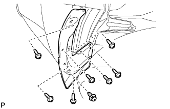 |
Remove the clip.
Using a T30 "TORX" socket, remove the 7 screws and mudguard.
| 7. REMOVE REAR BUMPER NO. 1 PLATE |
Put protective tape around the rear bumper No. 1 plate.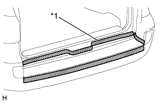
Text in Illustration *1
Protective Tape
Detach the 20 claws and remove the rear bumper No. 1 plate.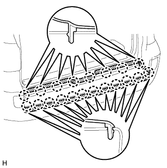
| 8. REMOVE REAR BUMPER COVER |
Remove the 6 screws, 2 clips and 2 bolts.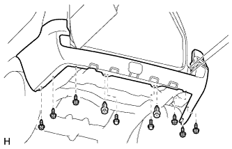
Remove the 2 clips and 5 bolts.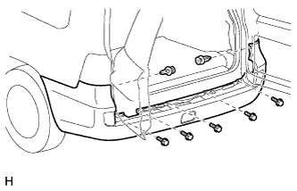
Put protective tape around the rear bumper cover.
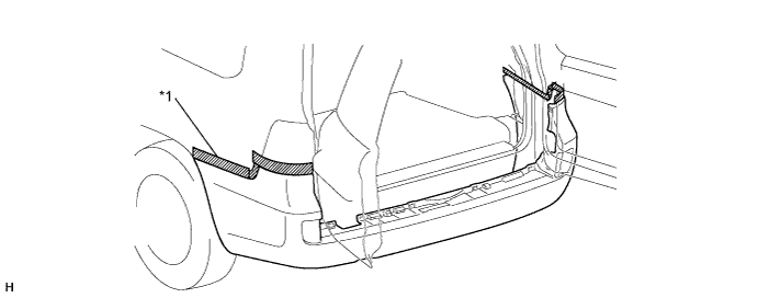
Text in Illustration *1
Protective Tape
-
-
Open the back doors one notch.
Disconnect the No. 2 frame wire connector.
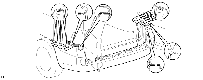
Detach the 14 claws and remove the rear bumper cover.
| 9. REMOVE REAR COMBINATION LIGHT ASSEMBLY LH |
Remove the 2 bolts.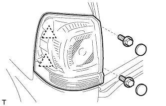
Detach the 2 clips and remove the rear combination light.
Disconnect the connector.
| 10. REMOVE REAR COMBINATION LIGHT ASSEMBLY RH |
- HINT:
- Use the same procedure described for the LH side.
| 11. REMOVE REAR BUMPER UPPER RETAINER LH |
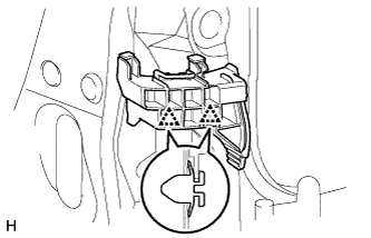 |
Detach the 2 clips and remove the rear bumper upper retainer.
| 12. REMOVE REAR BUMPER UPPER RETAINER RH |
- HINT:
- Use the same procedure described for the LH side.
| 13. REMOVE REAR BUMPER SIDE SUPPORT LH |
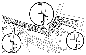 |
Remove the 3 screws.
Detach the 6 claws and remove the rear bumper side support.
| 14. REMOVE REAR BUMPER SIDE SUPPORT RH |
- HINT:
- Use the same procedure described for the LH side.
| 15. REMOVE REAR BUMPER NO. 2 REINFORCEMENT |
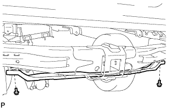 |
Remove the 2 bolts and rear bumper No. 2 reinforcement.
| 16. REMOVE REAR BUMPER ARM BRACKET |
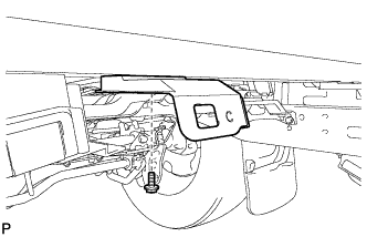 |
- HINT:
- Use the same procedure for both rear bumper arm brackets.
Remove the bolt and rear bumper arm bracket.
| 17. REMOVE REAR BUMPER ARM BRACKET LH |
Detach the clamp.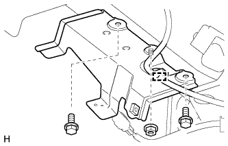
Remove the 2 bolts and nut and remove the rear bumper arm bracket.
| 18. REMOVE NO. 2 LUGGAGE COMPARTMENT SIDE COVER PROTECTOR |
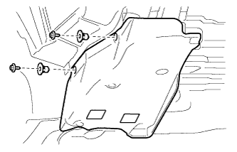 |
Remove the 2 screws, 2 grommets and No. 2 luggage compartment side cover protector.
| 19. REMOVE NO. 1 LUGGAGE COMPARTMENT SIDE COVER PROTECTOR |
- HINT:
- Use the same procedure described for the No. 2 luggage compartment side cover protector.