TERMINALS OF ECU
System information · Vehicles built Sep 2011 – Dec 2011
Versions by build date: Sep 2011 – Dec 2011 from Jan 2012
- HINT:
- Operating the ignition switch, any switches or any doors triggers related ECU and sensor communication with the CAN, which causes resistance variation.
| DISCONNECT CABLE FROM NEGATIVE BATTERY TERMINAL |
Disconnect the cable from the negative (-) battery terminal before measuring the resistances of the main wire and the branch wire.
- CAUTION:
- For vehicles with an SRS system:
- Wait at least 90 seconds after disconnecting the cable from the negative (-) battery terminal to disable the SRS system.
- NOTICE:
- Before measuring the resistance, leave the vehicle for at least 1 minute and do not operate the ignition switch, any switches or doors. If doors need to be opened in order to check connectors, open the doors and leave them open.
- When disconnecting the cable, some systems need to be initialized after the cable is reconnected (Click here).
- Before measuring the resistance, leave the vehicle for at least 1 minute and do not operate the ignition switch, any switches or doors. If doors need to be opened in order to check connectors, open the doors and leave them open.
| JUNCTION CONNECTOR |
NO. 1 JUNCTION CONNECTOR
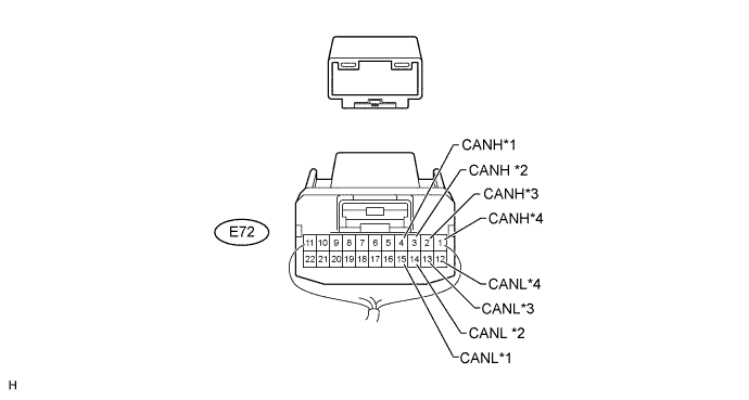

Text in Illustration *1
to Center Airbag Sensor (w/ Airbag System)
*2
to Main Body ECU: V Bus
*3
to ECM
*4
to No. 2 Junction Connector
No. 1 Junction Connector
Wiring Color
Connect to
E72-1 (CANH)
Y
No. 2 junction connector
E72-12 (CANL)
B
E72-2 (CANH)
P
ECM
E72-13 (CANL)
B
E72-3 (CANH)
SB
Main body ECU (cowl side junction block LH) (V bus)
E72-14 (CANL)
B
E72-4 (CANH)
GR
Center airbag sensor*
E72-15 (CANL)
B
- *: w/ Airbag System
- *: w/ Airbag System
NO. 2 JUNCTION CONNECTOR
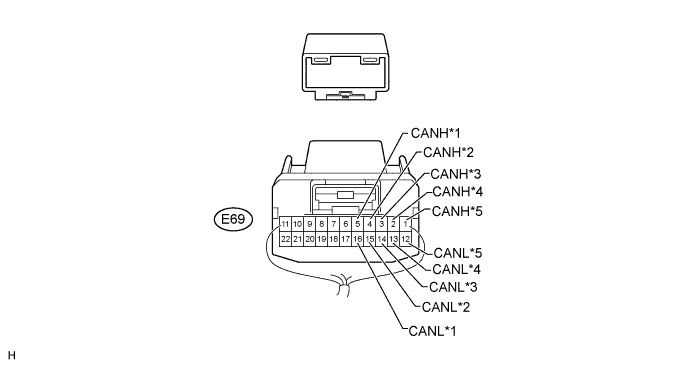
Text in Illustration *1
to Air Conditioning Amplifier
*2
to No. 1 Junction Connector
*3
to Network Gateway ECU: V Bus
*4
to Display and Navigation Module Display (w/ Navigation System)
*5
to No. 3 Junction Connector
-
-
No. 2 Junction Connector
Wiring Color
Connect to
E69-1 (CANH)
W
No. 3 junction connector
E69-12 (CANL)
B
E69-2 (CANH)*
P
Multi-display
E69-13 (CANL)*
B
E69-3 (CANH)
BR
Network gateway ECU (V bus)
E69-14 (CANL)
B
E69-4 (CANH)
Y
No. 1 junction connector
E69-15 (CANL)
B
E69-5 (CANH)
G
Air conditioning amplifier
E69-16 (CANL)
B
- *: w/ Navigation System
- *: w/ Navigation System
NO. 3 JUNCTION CONNECTOR
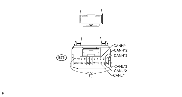
Text in Illustration *1
to Combination Meter: V Bus
*2
to DLC3
*3
to No. 2 Junction Connector
-
-
No. 3 Junction Connector
Wiring Color
Connect to
E75-1 (CANH)
W
No. 2 junction connector
E75-12 (CANL)
B
E75-2 (CANH)
G
DLC3
E75-13 (CANL)
B
E75-3 (CANH)
V
Combination meter (V bus)
E75-14 (CANL)
B
NO. 4 JUNCTION CONNECTOR
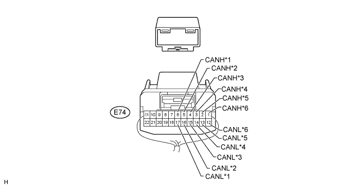
Text in Illustration *1
to 4WD Control ECU
*2
to Skid Control ECU
*3
to Steering Angle Sensor
*4
to Steering Control ECU
*5
to Network Gateway ECU: Movement Control Bus
*6
to No. 5 Junction Connector
No. 4 Junction Connector
Wiring Color
Connect to
E74-1 (CANH)
W
No. 5 junction connector
E74-12 (CANL)
L
E74-2 (CANH)
SB
Network gateway ECU (Movement control bus)
E74-13 (CANL)
L
E74-3 (CANH)*
LG
Steering control ECU
E74-14 (CANL)*
L
E74-4 (CANH)
GR
Steering angle sensor
E74-15 (CANL)
L
E74-5 (CANH)
V
Skid control ECU
E74-16 (CANL)
L
E74-6 (CANH)
P
4WD control ECU
E74-17 (CANL)
L
- *: w/ Variable Gear Ratio Steering System
- *: w/ Variable Gear Ratio Steering System
NO. 5 JUNCTION CONNECTOR
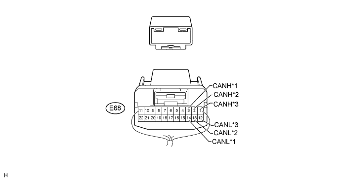
Text in Illustration *1
to Yaw Rate Sensor
*2
to No. 6 Junction Connector
*3
to No. 4 Junction Connector
-
-
No. 5 Junction Connector
Wiring Color
Connect to
E68-1 (CANH)
W
No. 4 junction connector
E68-12 (CANL)
L
E68-2 (CANH)
Y
No. 6 junction connector
E68-13 (CANL)
L
E68-3 (CANH)
BR
Yaw rate sensor
E68-14 (CANL)
L
NO. 6 JUNCTION CONNECTOR (except Double Swing Out Type)
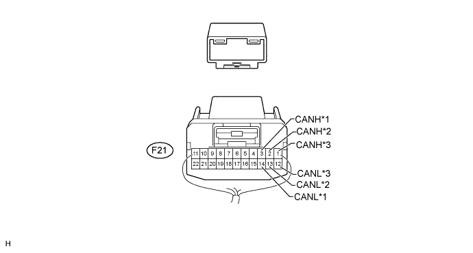
Text in Illustration *1
to No. 5 Junction Connector
*2
to No. 7 Junction Connector
*3
- to Clearance Warning ECU
(w/ TOYOTA Parking Assist-sensor System)
- to Parking Assist ECU
(w/ Parking Assist Monitor System)
-
-
No. 6 Junction Connector
Wiring Color
Connect to
F21-1 (CANH)*1
V
Clearance warning ECU
F21-12 (CANL)*1
L
F21-1 (CANH)*2
V
Parking assist ECU
F21-12 (CANL)*2
L
F21-2 (CANH)
W
No. 7 junction connector
F21-13 (CANL)
L
F21-3 (CANH)
Y
No. 5 junction connector
F21-14 (CANL)
L
- *1: w/ TOYOTA Parking Assist-sensor System
- *2: w/ Parking Assist Monitor System
- to Clearance Warning ECU
NO. 6 JUNCTION CONNECTOR (for Double Swing Out Type)
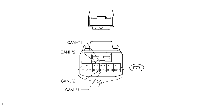
Text in Illustration *1
to No. 5 Junction Connector
*2
to No. 7 Junction Connector
No. 6 Junction Connector
Wiring Color
Connect to
F73-6 (CANH)
W
No. 7 junction connector
F73-17 (CANL)
L
F73-7 (CANH)
Y
No. 5 junction connector
F73-18 (CANL)
L
NO. 7 JUNCTION CONNECTOR
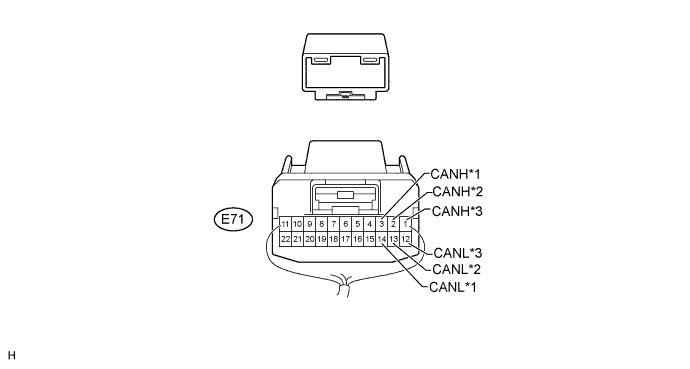
Text in Illustration *1
to No. 1 CAN Junction Connector
*2
to Seat Belt Control ECU (w/ Pre-Crash Safety System)
*3
to No. 6 Junction Connector
-
-
No. 7 Junction Connector
Wiring Color
Connect to
E71-1 (CANH)
W
No. 6 junction connector
E71-12 (CANL)
L
E71-2 (CANH)*
G
Seat belt control ECU
E71-13 (CANL)*
L
E71-3 (CANH)
W
No. 1 CAN junction connector
E71-14 (CANL)
L
- *: w/ Pre-Crash Safety System
- *: w/ Pre-Crash Safety System
NO. 8 JUNCTION CONNECTOR
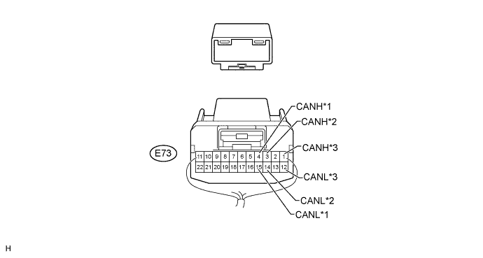
Text in Illustration *1
to Windshield Wiper ECU (w/ Rain Sensor)
*2
to Main body ECU: MS Bus
*3
to No. 2 CAN Junction Connector
-
-
No. 8 Junction Connector
Wiring Color
Connect to
E73-1 (CANH)
W
No. 2 CAN junction connector
E73-12 (CANL)
R
E73-3 (CANH)
GR
Main body ECU (cowl side junction block LH) (MS bus)
E73-14 (CANL)
R
E73-4 (CANH)*
LG
Windshield wiper ECU
E73-15 (CANL)*
R
- *: w/ Rain Sensor
- *: w/ Rain Sensor
NO. 9 JUNCTION CONNECTOR
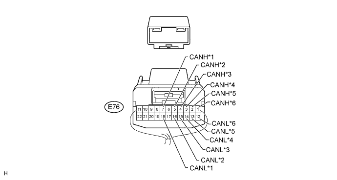
Text in Illustration *1
to No. 2 CAN Junction Connector
*2
to Outer Mirror Control ECU (w/ Seat Memory)
*3
to Position Control ECU and Switch (w/ Seat Memory)
*4
to Multiplex Tilt and Telescopic ECU (w/ Power Tilt and Power Telescopic Steering Column System)
*5
to Certification ECU (w/ Entry and Start System)
*6
to No. 10 Junction Connector
No. 9 Junction Connector
Wiring Color
Connect to
E76-1 (CANH)
W
No. 10 junction connector
E76-12 (CANL)
R
E76-2 (CANH)*1
LG
Certification ECU (smart key ECU assembly)
E76-13 (CANL)*1
R
E76-3 (CANH)*2
P
Multiplex tilt and telescopic ECU
E76-14 (CANL)*2
R
E76-4 (CANH)*3
V
Position control ECU and switch
E76-15 (CANL)*3
R
E76-5 (CANH)*3
BR
Outer mirror control ECU
E76-16 (CANL)*3
R
E76-7 (CANH)
Y
No. 2 CAN junction connector
E76-18 (CANL)
R
- *1: w/ Entry and Start System
- *2: w/ Power Tilt and Power Telescopic Steering Column System
- *3: w/ Seat Memory
- *1: w/ Entry and Start System
NO. 10 JUNCTION CONNECTOR
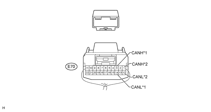
Text in Illustration *1
to No. 9 Junction Connector
*2
to Combination Meter: MS Bus
No. 10 Junction Connector
Wiring Color
Connect to
E70-1 (CANH)
W
No. 9 junction connector
E70-12 (CANL)
R
E70-3 (CANH)
LG
Combination meter (MS bus)
E70-14 (CANL)
R
NO. 1 CAN JUNCTION CONNECTOR
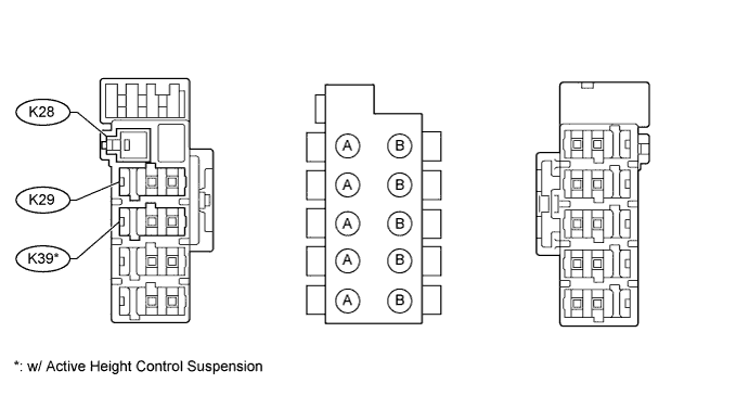
Junction Connector A Side
Wiring Color (CANH Side)
Wiring Color (CANL Side)
K28
-
W-B
No. 7 junction connector (K29)
W
L
Suspension control ECU (K39)*
V
L
- *: w/ Active Height Control Suspension
- *: w/ Active Height Control Suspension
NO. 2 CAN JUNCTION CONNECTOR
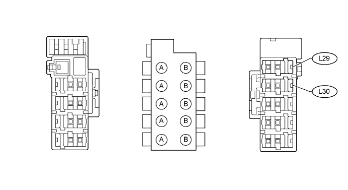
Junction Connector B Side
Wiring Color (CANH Side)
Wiring Color (CANL Side)
No. 8 junction connector (L29)
W
R
No. 9 junction connector (L30)
Y
R
| TERMINALS OF CONNECTORS FOR JUNCTION CONNECTOR (CAN JUNCTION CONNECTOR) |
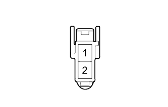 |
| Terminal No. |
Symbol |
| 1 |
CANH |
| 2 |
CANL |
| CHECK DLC3 |
Disconnect the cable from the negative (-) battery terminal before measuring the resistances of the main wire and the branch wire.
- NOTICE:
- When disconnecting the cable, some systems need to be initialized after the cable is reconnected (Click here).
Measure the resistance according to the value(s) in the table below.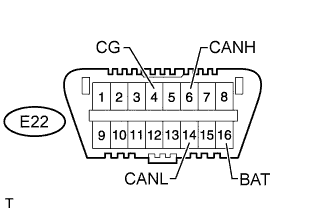
Terminal No. (Symbol)
Wiring Color
Switch Condition
Specified Condition
E22-6 (CANH) - E22-14 (CANL)
G - B
Ignition switch off
54 to 69 Ω
E22-6 (CANH) - E22-4 (CG)
G - W-B
Ignition switch off
200 Ω or higher
E22-14 (CANL) - E22-4 (CG)
B - W-B
Ignition switch off
200 Ω or higher
E22-6 (CANH) - E22-16 (BAT)
G - BE
Ignition switch off
6 kΩ or higher
E22-14 (CANL) - E22-16 (BAT)
B - BE
Ignition switch off
6 kΩ or higher
| CHECK SKID CONTROL ECU |
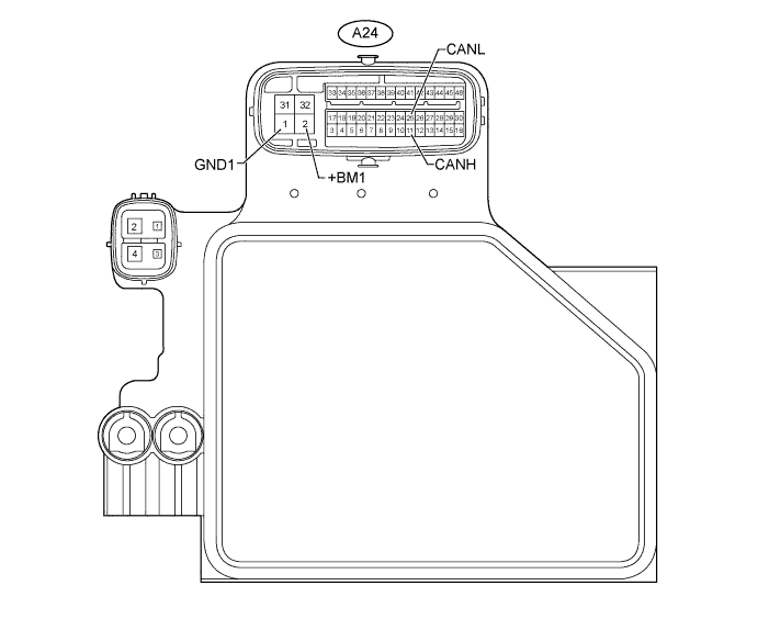
Disconnect the A24 ECU connector.
Measure the resistance according to the value(s) in the table below.
Terminal No. (Symbol)
Wiring Color
Switch Condition
Specified Condition
A24-11 (CANH) - A24-25 (CANL)
V - L
Ignition switch off
54 to 69 Ω
A24-11 (CANH) - A24-1 (GND1)
V - W-B
Ignition switch off
200 Ω or higher
A24-25 (CANL) - A24-1 (GND1)
L - W-B
Ignition switch off
200 Ω or higher
A24-11 (CANH) - A24-2 (+BM1)
V - B
Ignition switch off
6 kΩ or higher
A24-25 (CANL) - A24-2 (+BM1)
L - B
Ignition switch off
6 kΩ or higher
| CHECK AIR CONDITIONING AMPLIFIER (w/ REAR AIR CONDITIONING AMPLIFIER) |
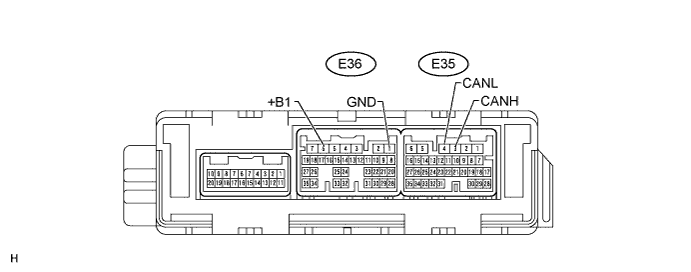
Measure the resistance according to the value(s) in the table below.
- HINT:
- Check from the rear of the connector while it is connected to the air conditioning amplifier.
Terminal No. (Symbol)
Wiring Color
Condition
Specified Condition
E35-3 (CANH) - E35-4 (CANL)
G - B
Ignition switch off
54 to 69 Ω
E35-3 (CANH) - E36-1 (GND)
G - W-B
Ignition switch off
200 Ω or higher
E35-4 (CANL) - E36-1 (GND)
B - W-B
E35-3 (CANH) - E36-6 (+B1)
G - R
Ignition switch off
6 kΩ or higher
E35-4 (CANL) - E36-6 (+B1)
B - R
| CHECK AIR CONDITIONING AMPLIFIER (w/o REAR AIR CONDITIONING AMPLIFIER) |
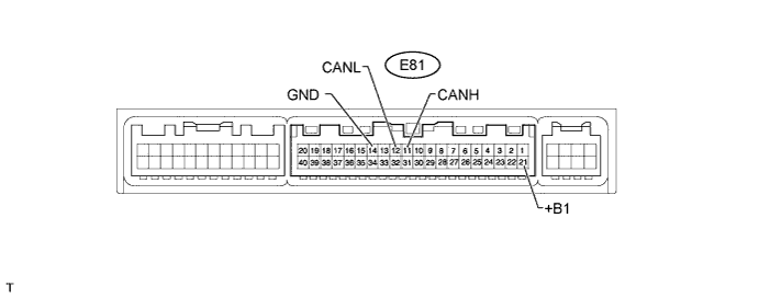
Disconnect the E81 ECU connector.
Measure the resistance according to the value(s) in the table below.
Terminal No. (Symbol)
Wiring Color
Switch Condition
Specified Condition
E81-11 (CANH) - E81-12 (CANL)
G - B
Ignition switch off
54 to 69 Ω
E81-11 (CANH) - E81-14 (GND)
G - W-B
Ignition switch off
200 Ω or higher
E81-12 (CANL) - E81-14 (GND)
B - W-B
Ignition switch off
200 Ω or higher
E81-11 (CANH) - E81-21 (+B1)
G - R
Ignition switch off
6 kΩ or higher
E81-12 (CANL) - E81-21 (+B1)
B - R
Ignition switch off
6 kΩ or higher
| CHECK ECM |
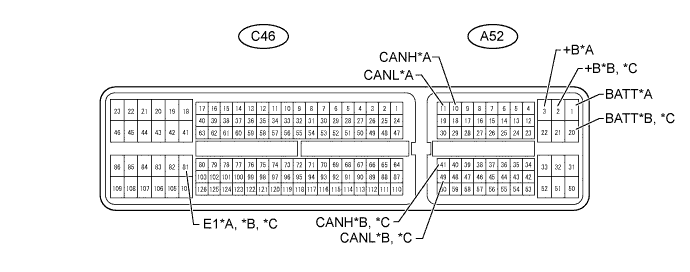
| *A |
for 2UZ-FE |
*B |
for 1GR-FE |
| *C |
for 1VD-FTV |
- |
- |
Disconnect the A52 and C46 ECM connectors.
Measure the resistance according to the value(s) in the table below.
Terminal No. (Symbol)
Wiring Color
Switch Condition
Specified Condition
A52-10 (CANH) - A52-11 (CANL)*1
P - B
Ignition switch off
108 to 132 Ω
A52-10 (CANH) - C46-81 (E1)*1
P - BR
Ignition switch off
200 Ω or higher
A52-11 (CANL) - C46-81 (E1)*1
B - BR
Ignition switch off
200 Ω or higher
A52-10 (CANH) - A52-3 (+B)*1
P - B
Ignition switch off
6 kΩ or higher
A52-11 (CANL) - A52-3 (+B)*1
B - B
Ignition switch off
6 kΩ or higher
A52-10 (CANH) - A52-1 (BATT)*1
P - L
Ignition switch off
6 kΩ or higher
A52-11 (CANL) - A52-1 (BATT)*1
B - L
Ignition switch off
6 kΩ or higher
A52-41 (CANH) - A52-49 (CANL)*2
P - B
Ignition switch off
108 to 132 Ω
A52-41 (CANH) - C46-81 (E1)*2
P - BR
Ignition switch off
200 Ω or higher
A52-49 (CANL) - C46-81 (E1)*2
B - BR
Ignition switch off
200 Ω or higher
A52-41 (CANH) - A52-2 (+B)*2
P - B
Ignition switch off
6 kΩ or higher
A52-49 (CANL) - A52-2 (+B)*2
B - B
Ignition switch off
6 kΩ or higher
A52-41 (CANH) - A52-20 (BATT)*2
P - L
Ignition switch off
6 kΩ or higher
A52-49 (CANL) - A52-20 (BATT)*2
B - L
Ignition switch off
6 kΩ or higher
A52-41 (CANH) - A52-49 (CANL)*3
P - B
Ignition switch off
108 to 132 Ω
A52-41 (CANH) - C46-81 (E1)*3
P - BR
Ignition switch off
200 Ω or higher
A52-49 (CANL) - C46-81 (E1)*3
B - BR
Ignition switch off
200 Ω or higher
A52-41 (CANH) - A52-20 (BATT)*3
P - L
Ignition switch off
6 kΩ or higher
A52-49 (CANL) - A52-20 (BATT)*3
B - L
Ignition switch off
6 kΩ or higher
A52-41 (CANH) - A52-2 (+B)*3
P - B
Ignition switch off
6 kΩ or higher
A52-49 (CANL) - A52-2 (+B)*3
B - B
Ignition switch off
6 kΩ or higher
- *1: for 2UZ-FE
- *2: for 1GR-FE
- *3: for 1VD-FTV
- *1: for 2UZ-FE
| CHECK MAIN BODY ECU (COWL SIDE JUNCTION BLOCK LH) |
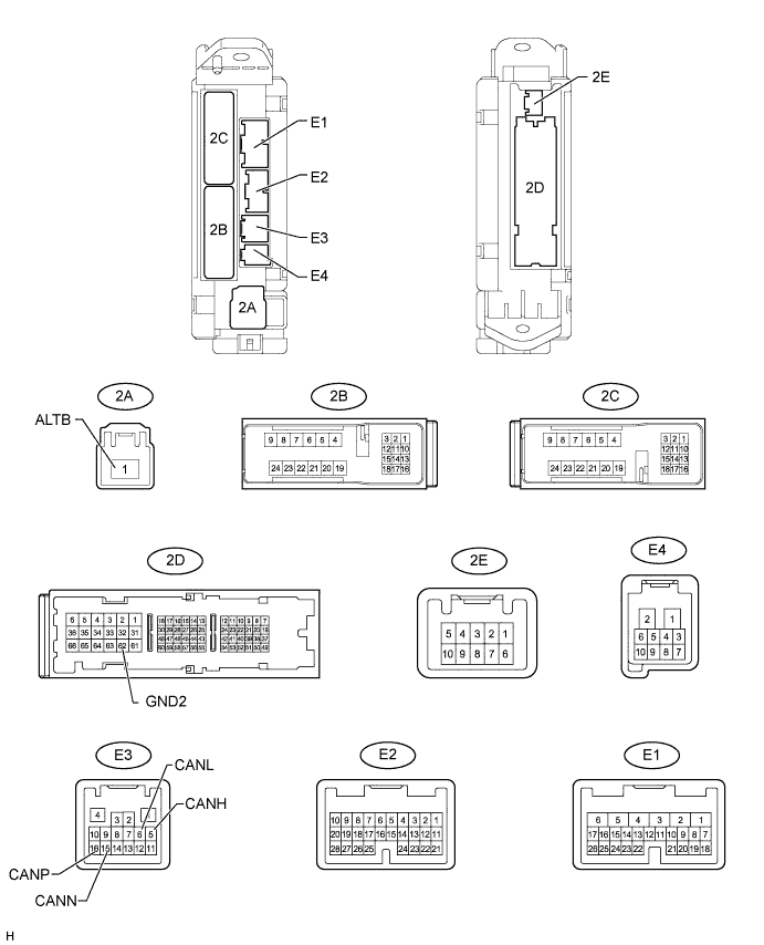
Disconnect the E3 ECU connector.
Disconnect the 2A and 2D junction connectors.
Measure the resistance according to the value(s) in the table below.
Terminal No. (Symbol)
Wiring Color
Switch Condition
Specified Condition
E3-5 (CANH) - E3-6 (CANL)*1
SB - B
Ignition switch off
54 to 69 Ω
E3-5 (CANH) - 2D-62 (GND2)*1
SB - W-B
Ignition switch off
200 Ω or higher
E3-6 (CANL) - 2D-62 (GND2)*1
B - W-B
Ignition switch off
200 Ω or higher
E3-5 (CANH) - 2A-1 (ALTB)*1
SB - B
Ignition switch off
6 kΩ or higher
E3-6 (CANL) - 2A-1 (ALTB)*1
B - B
Ignition switch off
6 kΩ or higher
E3-16 (CANP) - E3-15 (CANN)*2
GR - R
Ignition switch off
108 to 132 Ω
E3-16 (CANP) - 2D-62 (GND2)*2
GR - W-B
Ignition switch off
200 Ω or higher
E3-15 (CANN) - 2D-62 (GND2)*2
R - W-B
Ignition switch off
200 Ω or higher
E3-16 (CANP) - 2A-1 (ALTB)*2
GR - B
Ignition switch off
6 kΩ or higher
E3-15 (CANN) - 2A-1 (ALTB)*2
R - B
Ignition switch off
6 kΩ or higher
- *1: for V bus
- *2: for MS bus
- *1: for V bus
| CHECK COMBINATION METER |
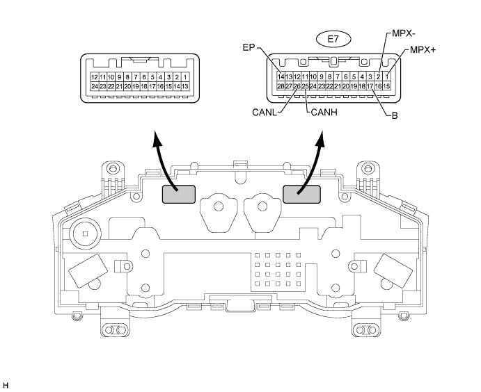
Disconnect the E7 ECU connector.
Measure the resistance according to the value(s) in the table below.
Terminal No. (Symbol)
Wiring Color
Switch Condition
Specified Condition
E7-25 (CANH) - E7-26 (CANL)*1
V - B
Ignition switch off
108 to 132 Ω
E7-25 (CANH) - E7-14 (EP)*1
V - W-B
Ignition switch off
200 Ω or higher
E7-26 (CANL) - E7-14 (EP)*1
B - W-B
Ignition switch off
200 Ω or higher
E7-25 (CANH) - E7-17 (B)*1
V - R
Ignition switch off
6 kΩ or higher
E7-26 (CANL) - E7-17 (B)*1
B - R
Ignition switch off
6 kΩ or higher
E7-1 (MPX+) - E7-2 (MPX-)*2
LG - R
Ignition switch off
108 to 132 Ω
E7-1 (MPX+) - E7-14 (EP)*2
LG - W-B
Ignition switch off
200 Ω or higher
E7-2 (MPX-) - E7-14 (EP)*2
R - W-B
Ignition switch off
200 Ω or higher
E7-1 (MPX+) - E7-17 (B)*2
LG - R
Ignition switch off
6 kΩ or higher
E7-2 (MPX-) - E7-17 (B)*2
R - R
Ignition switch off
6 kΩ or higher
- *1: for V bus
- *2: for MS bus
- *1: for V bus
| CHECK CENTER AIRBAG SENSOR (w/ Airbag System) |
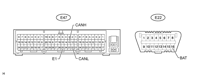
Disconnect the E47 sensor connector.
Measure the resistance according to the value(s) in the table below.
Terminal No. (Symbol)
Wiring Color
Switch Condition
Specified Condition
E47-13 (CANH) - E47-22 (CANL)
GR - B
Ignition switch off
54 to 69 Ω
E47-13 (CANH) - E47-25 (E1)
GR - W-B
Ignition switch off
200 Ω or higher
E47-22 (CANL) - E47-25 (E1)
B - W-B
Ignition switch off
200 Ω or higher
E47-13 (CANH) - E22-16 (BAT)
GR - BE
Ignition switch off
6 kΩ or higher
E47-22 (CANL) - E22-16 (BAT)
B - BE
Ignition switch off
6 kΩ or higher
| CHECK DISPLAY AND NAVIGATION MODULE DISPLAY |
- HINT:
- For vehicles with the navigation system only.
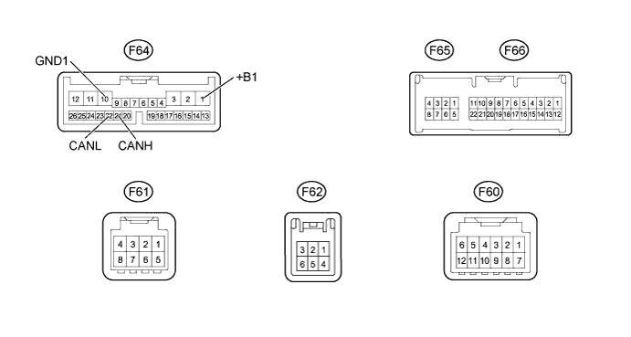
Disconnect the F64 display and navigation module display connector.
Measure the resistance according to the value(s) in the table below.
Terminal No. (Symbol)
Wiring Color
Switch Condition
Specified Condition
F64-21 (CANH) - F64-22 (CANL)
P - B
Ignition switch off
54 to 69 Ω
F64-21 (CANH) - F64-10 (GND1)
P - W-B
Ignition switch off
200 Ω or higher
F64-22 (CANL) - F64-10 (GND1)
B - W-B
Ignition switch off
200 Ω or higher
F64-21 (CANH) - F64-1 (+B1)
P - R
Ignition switch off
6 kΩ or higher
F64-22 (CANL) - F64-1 (+B1)
B - R
Ignition switch off
6 kΩ or higher
| CHECK STEERING ANGLE SENSOR |
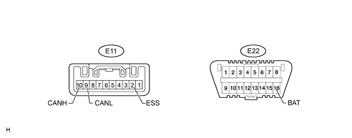
Disconnect the E11 sensor connector.
Measure the resistance according to the value(s) in the table below.
Terminal No. (Symbol)
Wiring Color
Switch Condition
Specified Condition
E11-10 (CANH) - E11-9 (CANL)
GR - L
Ignition switch off
54 to 69 Ω
E11-10 (CANH) - E11-2 (ESS)
GR - W-B
Ignition switch off
200 Ω or higher
E11-9 (CANL) - E11-2 (ESS)
L - W-B
Ignition switch off
200 Ω or higher
E11-10 (CANH) - E22-16 (BAT)
GR - BE
Ignition switch off
6 kΩ or higher
E11-9 (CANL) - E22-16 (BAT)
L - BE
Ignition switch off
6 kΩ or higher
| CHECK YAW RATE SENSOR |
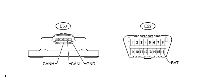
Disconnect the E50 sensor connector.
Measure the resistance according to the value(s) in the table below.
Terminal No. (Symbol)
Wiring Color
Switch Condition
Specified Condition
E50-3 (CANH) - E50-2 (CANL)
BR - L
Ignition switch off
54 to 69 Ω
E50-3 (CANH) - E50-1 (GND)
BR - W-B
Ignition switch off
200 Ω or higher
E50-2 (CANL) - E50-1 (GND)
L - W-B
Ignition switch off
200 Ω or higher
E50-3 (CANH) - E22-16 (BAT)
BR - BE
Ignition switch off
6 kΩ or higher
E50-2 (CANL) - E22-16 (BAT)
L - BE
Ignition switch off
6 kΩ or higher
| CHECK SEAT BELT CONTROL ECU |
- HINT:
- For vehicles with the pre-crash safety system only.
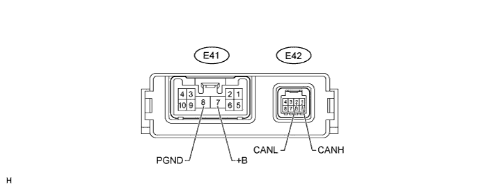
Disconnect the E41 and E42 ECU connectors.
Measure the resistance according to the value(s) in the table below.
Terminal No. (Symbol)
Wiring Color
Switch Condition
Specified Condition
E42-1 (CANH) - E42-2 (CANL)
G - L
Ignition switch off
54 to 69 Ω
E42-1 (CANH) - E41-8 (PGND)
G - W-B
Ignition switch off
200 Ω or higher
E42-2 (CANL) - E41-8 (PGND)
L - W-B
Ignition switch off
200 Ω or higher
E42-1 (CANH) - E41-7 (+B)
G - R
Ignition switch off
6 kΩ or higher
E42-2 (CANL) - E41-7 (+B)
L - R
Ignition switch off
6 kΩ or higher
| CHECK CLEARANCE WARNING ECU |
- HINT:
- For vehicles with the TOYOTA parking assist-sensor system only.
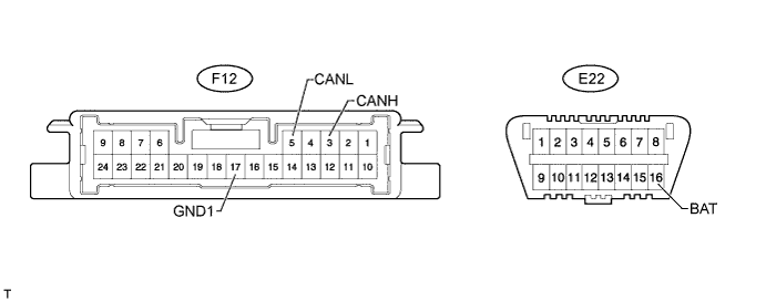
Disconnect the F12 ECU connector.
Measure the resistance according to the value(s) in the table below.
Terminal No. (Symbol)
Wiring Color
Switch Condition
Specified Condition
F12-3 (CANH) - F12-5 (CANL)
V - L
Ignition switch off
54 to 69 Ω
F12-3 (CANH) - F12-17 (GND1)
V - W-B
Ignition switch off
200 Ω or higher
F12-5 (CANL) - F12-17 (GND1)
L - W-B
Ignition switch off
200 Ω or higher
F12-3 (CANH) - E22-16 (BAT)
V - BE
Ignition switch off
6 kΩ or higher
F12-5 (CANL) - E22-16 (BAT)
L - BE
Ignition switch off
6 kΩ or higher
| CHECK OUTER MIRROR CONTROL ECU |
- HINT:
- For vehicles with the seat memory only.
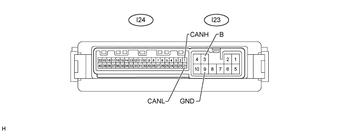
Disconnect the I23 and I24 ECU connectors.
Measure the resistance according to the value(s) in the table below.
Terminal No. (Symbol)
Wiring Color
Switch Condition
Specified Condition
I24-1 (CANH) - I24-21 (CANL)
BR - R
Ignition switch off
54 to 69 Ω
I24-1 (CANH) - I23-9 (GND)
BR - W-B
Ignition switch off
200 Ω or higher
I24-21 (CANL) - I23-9 (GND)
R - W-B
Ignition switch off
200 Ω or higher
I24-1 (CANH) - I23-3 (B)
BR - R
Ignition switch off
6 kΩ or higher
I24-21 (CANL) - I23-3 (B)
R - R
Ignition switch off
6 kΩ or higher
| CHECK MULTIPLEX TILT AND TELESCOPIC ECU |
- HINT:
- For vehicles with the power tilt and power telescopic steering column system only.
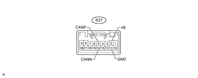
Disconnect the E27 ECU connector.
Measure the resistance according to the value(s) in the table below.
Terminal No. (Symbol)
Wiring Color
Switch Condition
Specified Condition
E27-5 (CANP) - E27-14 (CANN)
P - R
Ignition switch off
54 to 69 Ω
E27-5 (CANP) - E27-11 (GND)
P - W-B
Ignition switch off
200 Ω or higher
E27-14 (CANN) - E27-11 (GND)
R - W-B
Ignition switch off
200 Ω or higher
E27-5 (CANP) - E27-2 (+B)
P - L
Ignition switch off
6 kΩ or higher
E27-14 (CANN) - E27-2 (+B)
R - L
Ignition switch off
6 kΩ or higher
| CHECK CERTIFICATION ECU (SMART KEY ECU ASSEMBLY) |
- HINT:
- For vehicles with the entry and start system only.
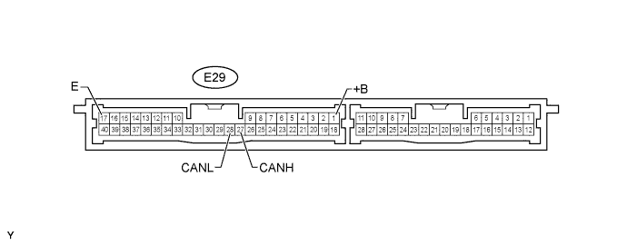
Disconnect the E29 ECU connector.
Measure the resistance according to the value(s) in the table below.
Terminal No. (Symbol)
Wiring Color
Switch Condition
Specified Condition
E29-27 (CANH) - E29-28 (CANL)
LG - R
Ignition switch off
54 to 69 Ω
E29-27 (CANH) - E29-17 (E)
LG - W-B
Ignition switch off
200 Ω or higher
E29-28 (CANL) - E29-17 (E)
R - W-B
Ignition switch off
200 Ω or higher
E29-27 (CANH) - E29-1 (+B)
LG - B
Ignition switch off
6 kΩ or higher
E29-28 (CANL) - E29-1 (+B)
R - B
Ignition switch off
6 kΩ or higher
| CHECK POSITION CONTROL ECU AND SWITCH |
- HINT:
- For vehicles with the seat memory only.
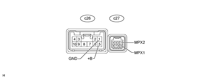
Disconnect the c26 and c27 ECU connectors.
Measure the resistance according to the value(s) in the table below.
Terminal No. (Symbol)
Wiring Color
Switch Condition
Specified Condition
c27-5 (MPX1) - c27-1 (MPX2)
V - R
Ignition switch off
54 to 69 Ω
c27-5 (MPX1) - c26-1 (GND)
V - W-B
Ignition switch off
200 Ω or higher
c27-1 (MPX2) - c26-1 (GND)
R - W-B
Ignition switch off
200 Ω or higher
c27-5 (MPX1) - c26-5 (+B)
V - L
Ignition switch off
6 kΩ or higher
c27-1 (MPX2) - c26-5 (+B)
R - L
Ignition switch off
6 kΩ or higher
| CHECK 4WD CONTROL ECU |
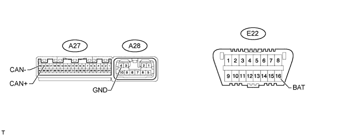
Disconnect the A27 and A28 ECU connectors.
Measure the resistance according to the value(s) in the table below.
Terminal No. (Symbol)
Wiring Color
Switch Condition
Specified Condition
A27-19 (CAN+) - A27-20 (CAN-)
P - L
Ignition switch off
54 to 69 Ω
A27-19 (CAN+) - A28-4 (GND)
P - W
Ignition switch off
200 Ω or higher
A27-20 (CAN-) - A28-4 (GND)
L - W
Ignition switch off
200 Ω or higher
A27-19 (CAN+) - E22-16 (BAT)
P - BE
Ignition switch off
6 kΩ or higher
A27-20 (CAN-) - E22-16 (BAT)
L - BE
Ignition switch off
6 kΩ or higher
| CHECK NETWORK GATEWAY ECU |

Disconnect the E31 ECU connector.
Measure the resistance according to the value(s) in the table below.
Terminal No. (Symbol)
Wiring Color
Switch Condition
Specified Condition
E31-16 (CA1H) - E31-15 (CA1L)*1
BR - B
Ignition switch off
54 to 69 Ω
E31-16 (CA1H) - E31-4 (GND)*1
BR - W-B
Ignition switch off
200 Ω or higher
E31-15 (CA1L) - E31-4 (GND)*1
B - W-B
Ignition switch off
200 Ω or higher
E31-16 (CA1H) - E31-2 (BATT)*1
BR - R
Ignition switch off
6 kΩ or higher
E31-15 (CA1L) - E31-2 (BATT)*1
B - R
Ignition switch off
6 kΩ or higher
E31-13 (CA2H) - E31-12 (CA2L)*2
SB - L
Ignition switch off
108 to 132 Ω
E31-13 (CA2H) - E31-4 (GND)*2
SB - W-B
Ignition switch off
200 Ω or higher
E31-12 (CA2L) - E31-4 (GND)*2
L - W-B
Ignition switch off
200 Ω or higher
E31-13 (CA2H) - E31-2 (BATT)*2
SB - R
Ignition switch off
6 kΩ or higher
E31-12 (CA2L) - E31-2 (BATT)*2
L - R
Ignition switch off
6 kΩ or higher
- *1: for V bus
- *2: for Movement control bus
- *1: for V bus
| CHECK STEERING CONTROL ECU |
- HINT:
- For vehicles with the variable gear ratio steering system only.
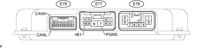
Disconnect the E77 and E79 ECU connectors.
Measure the resistance according to the value(s) in the table below.
Terminal No. (Symbol)
Wiring Color
Switch Condition
Specified Condition
E79-9 (CANH) - E79-20 (CANL)
LG - L
Ignition switch off
54 to 69 Ω
E79-9 (CANH) - E77-7 (PGND)
LG - W-B
Ignition switch off
200 Ω or higher
E79-20 (CANL) - E77-7 (PGND)
L - W-B
Ignition switch off
200 Ω or higher
E79-9 (CANH) - E77-10 (+B1)
LG - R
Ignition switch off
6 kΩ or higher
E79-20 (CANL) - E77-10 (+B1)
L - R
Ignition switch off
6 kΩ or higher
| CHECK SUSPENSION CONTROL ECU |
- HINT:
- For vehicles with the active height control suspension only.
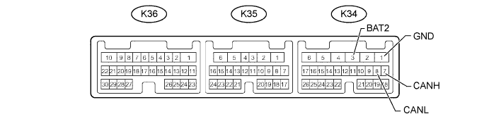
Disconnect the K34 suspension control ECU connector.
Measure the resistance according to the value(s) in the table below.
Terminal No. (Symbol)
Wiring Color
Switch Condition
Specified Condition
K34-7 (CANH) - K34-8 (CANL)
V - L
Ignition switch off
54 to 69 Ω
K34-7 (CANH) - K34-1 (GND)
V - W-B
Ignition switch off
200 Ω or higher
K34-8 (CANL) - K34-1 (GND)
L - W-B
Ignition switch off
200 Ω or higher
K34-7 (CANH) - K34-3 (BAT2)
V - R
Ignition switch off
6 kΩ or higher
K34-8 (CANL) - K34-3 (BAT2)
L - R
Ignition switch off
6 kΩ or higher
| CHECK WINDSHIELD WIPER ECU |
- HINT:
- For vehicles with the rain sensor only.
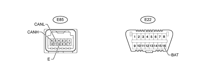
Disconnect the E85 windshield wiper ECU connector.
Measure the resistance according to the value(s) in the table below.
Terminal No. (Symbol)
Wiring Color
Switch Condition
Specified Condition
E85-6 (CANH) - E85-5 (CANL)
LG - R
Ignition switch off
54 to 69 Ω
E85-6 (CANH) - E85-10 (E)
LG - W-B
Ignition switch off
200 Ω or higher
E85-5 (CANL) - E85-10 (E)
R - W-B
Ignition switch off
200 Ω or higher
E85-6 (CANH) - E22-16 (BAT)
LG - BE
Ignition switch off
6 kΩ or higher
E85-5 (CANL) - E22-16 (BAT)
R - BE
Ignition switch off
6 kΩ or higher
| CHECK PARKING ASSIST ECU |
- HINT:
- For vehicles with the parking assist monitor system only.
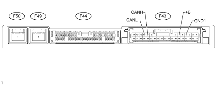
Disconnect the F43 parking assist ECU connector.
Measure the resistance according to the value(s) in the table below.
Terminal No. (Symbol)
Wiring Color
Switch Condition
Specified Condition
F43-9 (CANH) - F43-10 (CANL)
V - L
Ignition switch off
54 to 69 Ω
F43-9 (CANH) - F43-4 (GND1)
V - W-B
Ignition switch off
200 Ω or higher
F43-10 (CANL) - F43-4 (GND1)
L - W-B
Ignition switch off
200 Ω or higher
F43-9 (CANH) - F43-6 (+B)
V - L
Ignition switch off
6 kΩ or higher
F43-10 (CANL) - F43-6 (+B)
L - L
Ignition switch off
6 kΩ or higher