INSTALLATION
Removal / installation · Vehicles built Sep 2011 – Dec 2011
Versions by build date: Sep 2011 – Dec 2011 from Jan 2012
| 1.
INSTALL V-RIBBED BELT |
 |
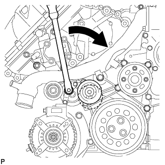
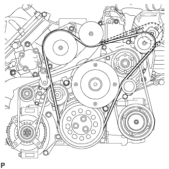
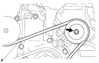
- Attach a wrench to the V-ribbed belt tensioner bracket and turn the wrench clockwise.
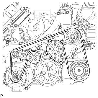
- Install the V-ribbed belt as shown in the illustration.
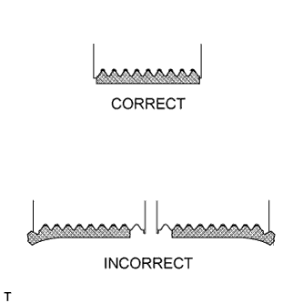
- Check that the belt fits properly in the ribbed grooves.
- HINT:
- Check with your hand to confirm that the belt has not slipped out of the groove on the bottom of the pulley.
- If it has slipped out, replace the V-ribbed belt. Install a new V-ribbed belt.
| 2.
INSTALL NO. 3 IDLER PULLEY (w/ Viscous Heater) |
|
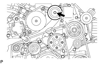
- Align the No. 3 idler pulley bracket knock pin and No. 1 idler pulley bracket knock pin hole and install the No. 3 idler pulley with the nut.
-
Torque:
- 88 N*m{
898 kgf*cm
, 64 ft.*lbf
}
| 3.
INSTALL NO. 1 IDLER PULLEY (w/ Viscous Heater) |
|
- Install the collar, No. 1 idler pulley and cover with the bolt.
-
Torque:
- 49 N*m{
495 kgf*cm
, 36 ft.*lbf
}
| 4.
INSTALL V-RIBBED BELT (w/ Viscous Heater) |
|
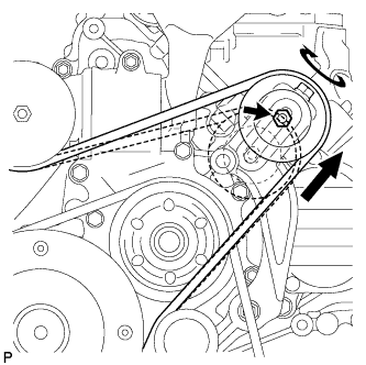
- Install the V-ribbed belt as shown in the illustration.
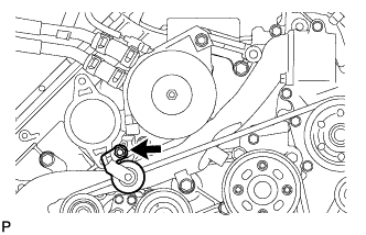
- Temporarily install the lock nut, and turn the bolt clockwise.
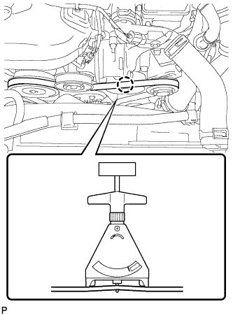
- Using a belt tension gauge, adjust belt tension.
- Standard Belt Tension:
Item
|
Specified Condition
|
New belt
|
400 to 650 N (41 to 66 kgf, 89.9 to 146.1 lbf)
|
Used belt
|
300 to 500 N (31 to 51 kgf, 67.4 to 112.4 lbf)
|
- HINT:
- A "new belt" is a belt which has been used for less than 5 minutes on a running engine.
- A "used belt" is a belt which has been used on a running engine for 5 minutes or more.
- After installing a new belt, run the engine for approximately 5 minutes and then recheck the tension.
- Tighten the nut.
-
Torque:
- 40 N*m{
408 kgf*cm
, 30 ft.*lbf
}
- Check that the belt fits properly in the ribbed grooves.
- HINT:
- Check with your hand to confirm that the belt has not slipped out of the groove on the bottom of the pulley.
- If it has slipped out, replace the V-ribbed belt. Install a new V-ribbed belt.
| 5.
INSTALL INTAKE AIR CONNECTOR
|
|
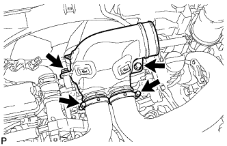
- Connect the intake air connector to the No. 1 and No. 2 air cleaner pipes.
Install the connector with the 2 bolts.
-
Torque:
- 21 N*m{
214 kgf*cm
, 15 ft.*lbf
}
Tighten the 2 hose clamps.
-
Torque:
- 6.3 N*m{
64 kgf*cm
, 56 in.*lbf
}
- Attach the 3 wire harness clamps.
w/o Viscous Heater:
Connect the connector to the water temperature sensor.
w/ Viscous Heater:
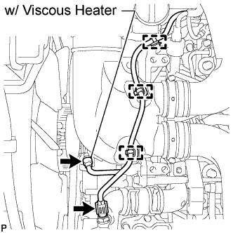
Connect the 2 connectors to the water temperature sensor and viscous with magnet clutch heater.
| 6.
TEMPORARILY INSTALL NO. 1 AIR CLEANER HOSE
|
|
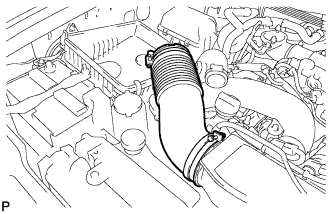
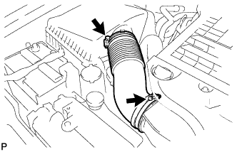
- Temporarily install the air cleaner hose to the intake air connector.
| 7.
INSTALL AIR CLEANER CAP SUB-ASSEMBLY
|
|
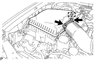
- Connect the air cleaner cap to the air cleaner hose, and install the air cleaner cap with the 4 clamps.
Connect the mass air flow meter connector and attach the wire harness clamp to the air cleaner cap.
Attach the wire harness clamp.
- Align the protrusion of air cleaner cap and concave portion of air cleaner hose.
Tighten the 2 hose clamps.
-
Torque:
- 5.0 N*m{
51 kgf*cm
, 44 in.*lbf
}
| 8.
INSTALL NO. 1 ENGINE COVER SUB-ASSEMBLY (w/ Intercooler)
|
|
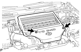
- Install the engine cover with the 2 nuts.
-
Torque:
- 8.0 N*m{
82 kgf*cm
, 71 in.*lbf
}
| 9.
INSTALL UPPER RADIATOR SUPPORT SEAL
|
|
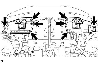
Install the upper radiator support seal with the 7 clips.
| 10.
INSTALL NO. 1 ENGINE UNDER COVER SUB-ASSEMBLY
|
|
- Install the engine under cover with the 10 bolts.
-
Torque:
- 29 N*m{
296 kgf*cm
, 21 ft.*lbf
}
| 11.
INSTALL FRONT FENDER SPLASH SHIELD SUB-ASSEMBLY RH
|
|
- Install the splash shield with the clip, and then install the 3 bolts and screw.
| 12.
INSTALL FRONT FENDER SPLASH SHIELD SUB-ASSEMBLY LH
|
|
Install the splash shield with the clip, and then install the 3 bolts and screw.