DISASSEMBLY
Removal / installation · Vehicles built from Jan 2012
Versions by build date: Sep 2011 – Dec 2011 from Jan 2012
| 1. REMOVE BLOWER ASSEMBLY |

| 2. REMOVE NO. 4 AIR DUCT SUB-ASSEMBLY |
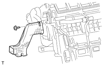  |
Remove the screw and duct.
| 3. REMOVE NO. 5 AIR DUCT SUB-ASSEMBLY |
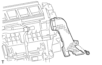 |
Remove the screw and duct.
| 4. REMOVE ASPIRATOR (for Automatic Air Conditioning System) |
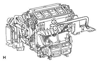 |
Detach the 2 claws and remove the aspirator.
| 5. REMOVE COOL BOX LIQUID TUBE (w/ Cool Box) |
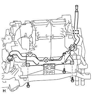 |
Remove the 3 screws.
Detach the 2 claws and remove the protective cover.
Using SST, remove the piping clamp.
- SST
- 09870-00025
Attach SST to the piping clamp.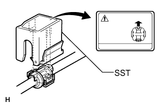
- HINT:
- Confirm the direction of the piping clamp claw and SST by referring to the illustration on the caution label.
Push down SST and release the clamp lock.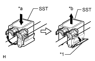
- NOTICE:
- Be careful not to deform the tubes when pushing SST.
Pull SST slightly and push the release lever, then remove the piping clamp with SST.
Remove the piping clamp from SST.
Text in Illustration *1
Release Lever
*a
Push
*b
Pull
Disconnect the tube.
- NOTICE:
- Cap the open fittings immediately to keep moisture or dirt out of the system.
Detach the clamp and remove the liquid tube.
Remove the 2 O-rings from the liquid tube.
| 6. REMOVE QUICK HEATER ASSEMBLY (w/ PTC Heater) |
Remove the 2 screws.
Detach the 3 clamps and remove the quick heater assembly (PTC heater assembly).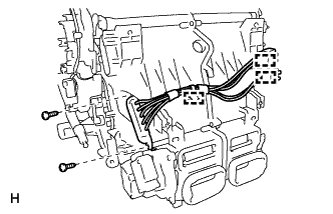
| 7. REMOVE AIR CONDITIONER HARNESS |
Disconnect the connectors.
Detach the 2 clamps and remove the harness.
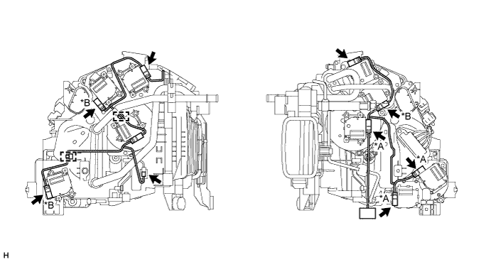
Text in Illustration *A
for Automatic Air Conditioning System
*B
for 4 Zone Type
| 8. REMOVE AIR CONDITIONING RADIATOR ASSEMBLY |
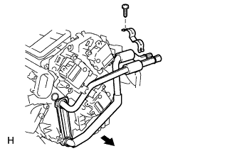 |
Remove the screw and radiator bracket.
Remove the radiator.
| 9. REMOVE COOLER EXPANSION VALVE (w/ Cool Box) |
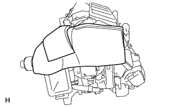 |
Remove the packing.
Remove the butyl tape.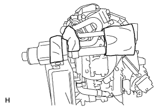
Using a 4 mm hexagon wrench, remove the hexagon bolt, screw and bracket.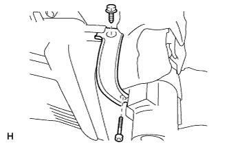
Using a 4 mm hexagon wrench, remove the 2 hexagon bolts and No. 1 connector tube.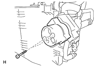
Remove the 2 O-rings from the No. 1 connector tube.
Using a 4 mm hexagon wrench, remove the 2 hexagon bolts, No. 2 connector tube, expansion valve and No. 3 connector tube.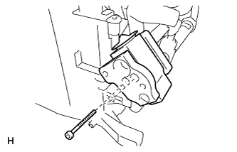
Remove the 2 O-rings from the No. 2 connector tube.
| 10. REMOVE AIR CONDITIONER TUBE AND ACCESSORY ASSEMBLY (w/ Cool Box) |
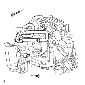 |
Remove the screw and bracket.
Using a 4 mm hexagon wrench, remove the 2 hexagon bolts and air conditioner tube and accessory assembly.
Remove the 2 O-rings from the air conditioner tube and accessory assembly.
| 11. REMOVE COOLER EXPANSION VALVE (w/o Cool Box) |
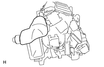 |
Remove the packing.
Using a 4 mm hexagon wrench, remove the 2 hexagon bolts, air conditioner tube and accessory assembly and expansion valve.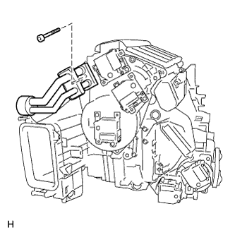
Remove the 2 O-rings from the air conditioner tube and accessory assembly.
Remove the 2 O-rings from the cooler evaporator.
| 12. REMOVE REAR AIR MIX DAMPER CONTROL SERVO MOTOR RH (for 4 Zone Type) |
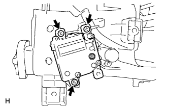 |
Remove the 3 screws and servo motor.
| 13. REMOVE SERVO MOTOR |
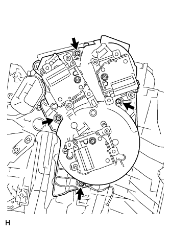 |
Remove the 4 screws and servo motor unit.
for 4 Zone Type: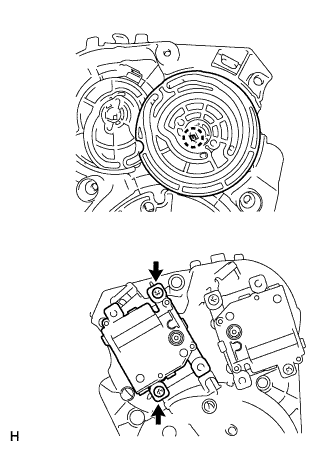
Remove the front mode control servo motor RH.Remove the 2 screws.
Detach the claw and remove the plate and servo motor.
- NOTICE:
- Be careful not to damage the claw of the plate.
Remove the control air bypass damper control servo motor RH.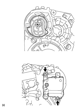
Remove the 2 screws.
Detach the claw and remove the plate and servo motor.
- NOTICE:
- Be careful not to damage the claw of the plate.
Remove the front air mix damper control servo motor RH.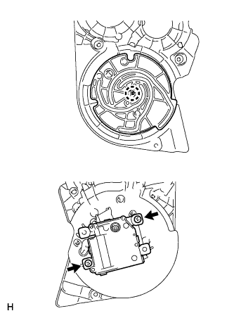
Remove the 2 screws.
Detach the claw and remove the plate and servo motor.
- NOTICE:
- Be careful not to damage the claw of the plate.
| 14. REMOVE SERVO MOTOR |
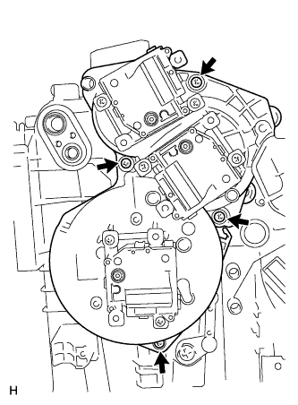 |
Remove the 4 screws and servo motor unit.
for 4 Zone Type: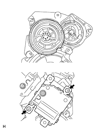
Remove the control air bypass damper control servo motor LHRemove the 2 screws.
Detach the claw and remove the plate.
- NOTICE:
- Be careful not to damage the claw of the plate.
Remove the front mode control servo motor LH.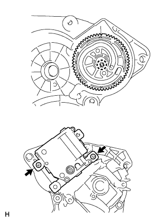
Remove the 2 screws.
Detach the claw and remove the plate and servo motor.
- NOTICE:
- Be careful not to damage the claw of the plate.
Remove the front air mix damper control servo motor LH.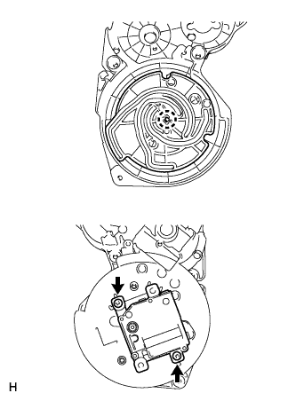
Remove the 2 screws.
Detach the claw and remove the plate and servo motor.
- NOTICE:
- Be careful not to damage the claw of the plate.
| 15. REMOVE SERVO MOTOR |
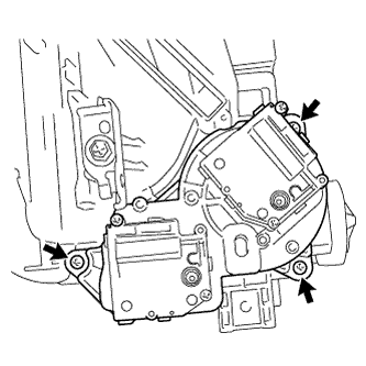 |
Remove the 3 screws and servo motor unit.
Remove the rear mode control servo motor.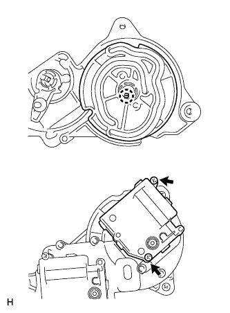
Remove the 2 screws.
Detach the claw and remove the plate and servo motor.
- NOTICE:
- Be careful not to damage the claw of the plate.
Remove the rear air mix damper control servo motor LH.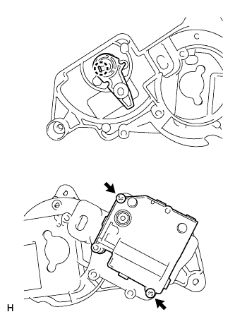
Remove the 2 screws.
Detach the claw and remove the lever and servo motor.
- NOTICE:
- Be careful not to damage the claw of the lever.
| 16. REMOVE NO. 1 COOLER EVAPORATOR SUB-ASSEMBLY |
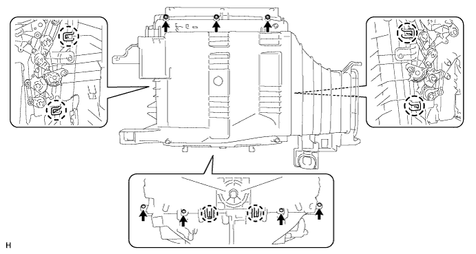
Remove the 7 screws.
Detach the 6 claws and remove the unit case.
Remove the evaporator.
| 17. REMOVE FRONT EVAPORATOR TEMPERATURE SENSOR |
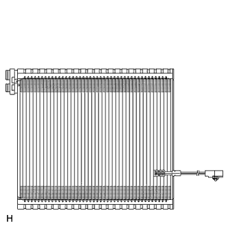 |
Remove the front evaporator temperature sensor.