INSTALLATION
Removal / installation · Vehicles built from Jan 2012
| 1. INSTALL AIR PUMP |

Install the 3 insulators to the air pump.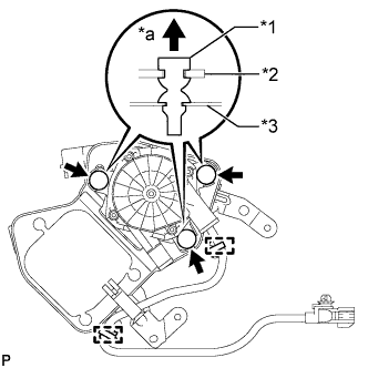

Text in Illustration *1
Insulator
*2
Air Pump
*3
Air Pump Bracket
*a
Top
Attach the 2 wire harness clamps to the air pump bracket.
| 2. INSTALL NO. 1 AIR INJECTION SYSTEM HOSE |
Install the No. 1 air injection system hose to the air pump assembly.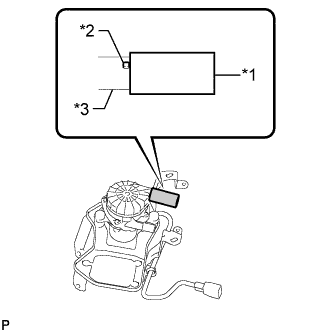
Text in Illustration *1
No. 1 Air Injection System Hose
*2
Protrusion
*3
Air Pump Assembly
- HINT:
- Push the No. 1 air injection system hose onto the air pump assembly until it contacts the protrusion as shown in the illustration.
| 3. INSTALL AIR PUMP INLET |
Install the air pump inlet to the No. 1 air injection system hose.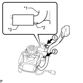
Text in Illustration *1
Air Pump Inlet
*2
Stopper
*3
No. 1 Air Injection System Hose
- HINT:
- Insert the air pump inlet until its stopper contacts the No. 1 air injection system hose as shown in the illustration.
Install the 2 bolts and tighten them in the order shown in the illustration.
- Torque:
- 8.0 N*m{ 82 kgf*cm , 71 in.*lbf }
| 4. INSTALL AIR PUMP ASSEMBLY |
Attach the claw of the air pump bracket to the elongated hole in the body to position the air pump bracket.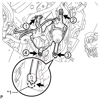
Text in Illustration *1
Claw
Install the 2 bolts and 2 nuts and tighten them in the order shown in the illustration.
- Torque:
- 18 N*m{ 184 kgf*cm , 13 ft.*lbf }
Connect the wire harness to the clamp at the location shown in the illustration.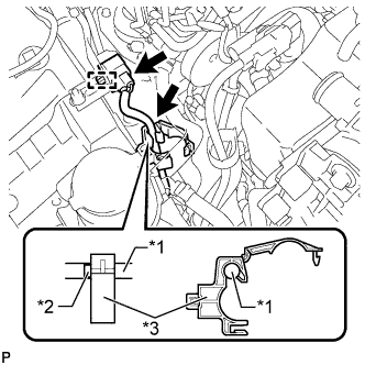
Text in Illustration *1
Wire Harness
*2
Paint Mark
*3
Clamp
Attach the connector clamp to the bracket.
Connect the connector.
| 5. INSTALL NO. 3 AIR INJECTION SYSTEM HOSE |
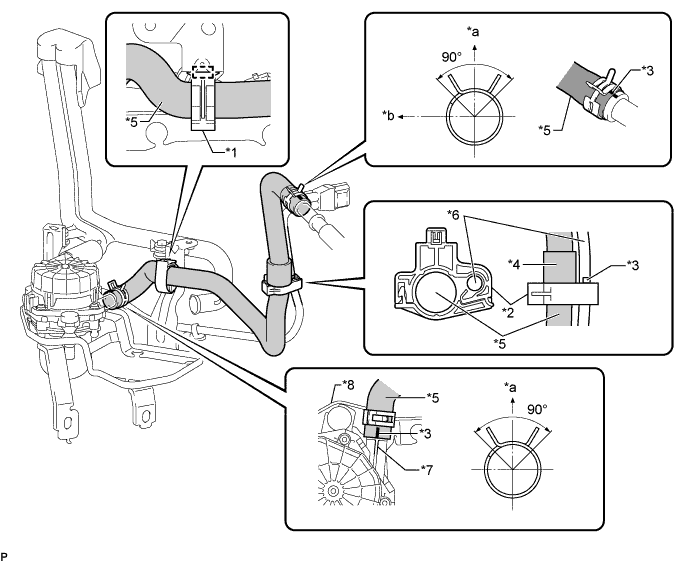
| *1 |
Clamp A |
*2 |
Clamp B |
| *3 |
Paint Mark |
*4 |
Protector |
| *5 |
No. 3 Air Injection System Hose |
*6 |
Wire Harness |
| *7 |
Protrusion |
*8 |
Air Pump Assembly |
| *a |
Top |
*b |
Front |
Inside front fender RH:
Connect the No. 3 air injection system hose to the air pump assembly at the location shown in the illustration.
- HINT:
- Align the paint mark of the No. 3 air injection system hose with the protrusion of the air pump assembly.
Attach clamp A to the air pump bracket.
Inside engine room:
Connect the No. 3 air injection system hose to the air tube at the location shown in the illustration.
Align the bottom edge of the protector of the No. 3 air injection system hose with clamp B and attach the clamp.
| 6. CONNECT FRONT FENDER LINER RH |
Install the fender liner with the 4 clips.
Using a T30 "TORX" socket, install the 2 screws.
Connect the liner to the front bumper cover with the screw.
| 7. INSTALL FRONT FENDER APRON TRIM PACKING A |
Install the front fender apron trim packing A with the 3 clips.
| 8. INSTALL FRONT FENDER SPLASH SHIELD SUB-ASSEMBLY RH |
Push in the clip to install the front fender splash shield sub-assembly RH.
Install the 3 bolts and 2 screws.