SEAT SEAT ASSEMBLY DETAILS REAR SEAT
CONSTRUCTION
Rear No. 1 Seat
The reclining position of the rear No. 1 seat can be adjusted using the tumble fold lever.
The tumble fold lever is structured so that it can be operated even from the rear No. 2 seat side.
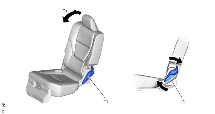
| *1 | Tumble Fold Lever | - | - |
| *a | Seat Reclining | *b | The illustration shown is example only. |
| Function | Rear No. 1 Seat |
| Seat Reclining | Approximately 28° |
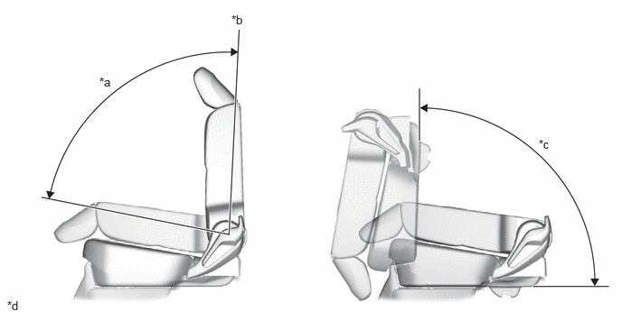
| *a | Forward Collapse Trajectory | *b | Upright |
| *c | Tumble Trajectory | *d | The illustration shown is example only. |
| Operation | Rear No. 1 Seat |
| Forward Collapse Trajectory | Approximately 86° |
| Tumble Trajectory | Approximately 90° |
A lock to keep the size of the gap minimized is used as the fixing lock for the rear No. 1 seat.*
- HINT:
-
*: The lock has a structure where the hook is followed by a cam and the floor striker is always supported at 3 points (a, b and c) to control rattling.
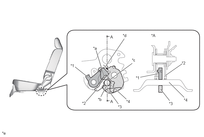
| *A | A-A | - | - |
| *1 | Cam | *2 | Base |
| *3 | Hook | *4 | Floor Striker |
| *a | Point a | *b | Point b |
| *c | Point c | *d | Pushed in |
| *e | The illustration shown is example only. | - | - |
The seat frame is optimized, achieving weight reduction of the rear No. 1 seat.
High-tensile strength steel is used to reduce the sheet thickness.
The center back lock is located on the upper end to reduce the load on the center back frame and simplify the frame structure.
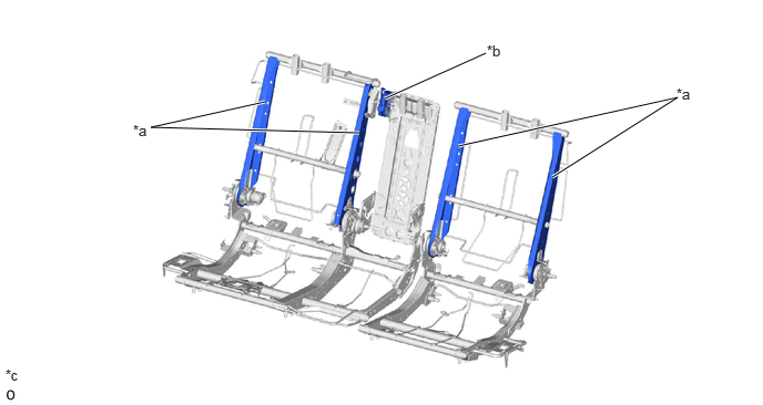
| *a | High-tensile Strength Steel | *b | Center Back Lock |
| *c | The illustration shown is example only. | - | - |
Child Restraint System
An ISO-FIX Bar (child restraint seat anchor bracket sub-assembly) for securing child seats has been provided behind the rear No. 1 seat cushion.
The top tether anchor bars are provided behind the rear No. 1 seat back.
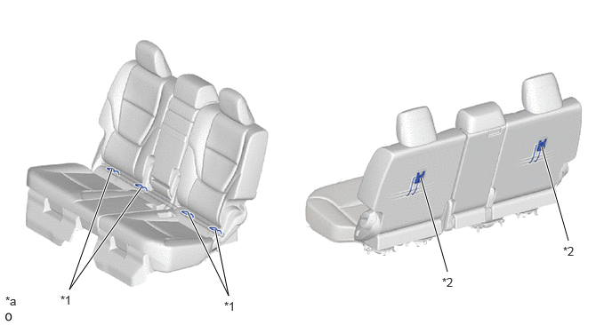
| *1 | ISO-FIX Bar (Child Restraint Seat Anchor Bracket Sub-assembly) | *2 | Top Tether Anchor Bar |
| *a | The illustrations shown are examples only. | - | - |
Rear No. 2 Seat (Models with rear No. 2 seat)
A reclining function is provided for the rear No. 2 seat.
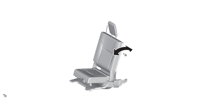
| *a | Seat Reclining | *b | The illustrations shown are examples only. |
| Function | Manual Seat | Power Seat |
| Seat Reclining | Approximately 14° | Approximately 10° |
The new structure allows folding operations for the manual seat in the upright condition to be completed in just 2 motions.
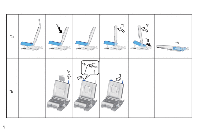
| *a | Seat movement | *b | Seat folding operation |
| *c | Fold down the headrest | *d | Pull the strap upward to unlock the headrest |
| *e | Lift up the shoulder lever | *f | Push the seatback forward |
| *g | Seat cushion starts folding with the seatback | *h | Folding is completed |
| *i | The illustrations shown are examples only. | - | - |

|
Automatic |

|
Manual |
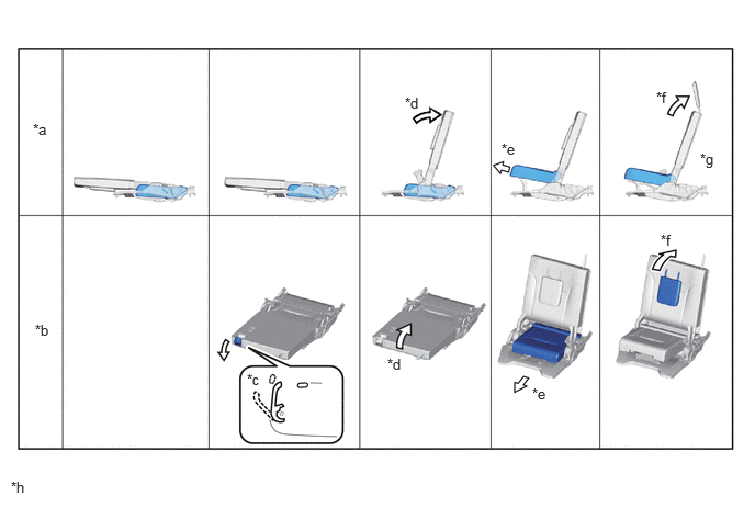
| *a | Seat movement | *b | Seat return operation |
| *c | Lift up the shoulder lever | *d | Lift the upper seatback up |
| *e | Pull the cushion lever to return to the sitting position | *f | Lift up the headrest |
| *g | Ready for use as seat | *h | The illustrations shown are examples only. |
|
|
Manual | - | - |
The seat frame is optimized, achieving weight reduction of the rear No. 2 seat.
High-tensile strength steel is used to reduce the sheet thickness.
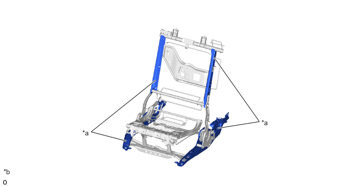
| *a | High-tensile Strength Steel | *b | The illustration shown is example only. |
A rope hook assembly is provided on outer side of each seatback.
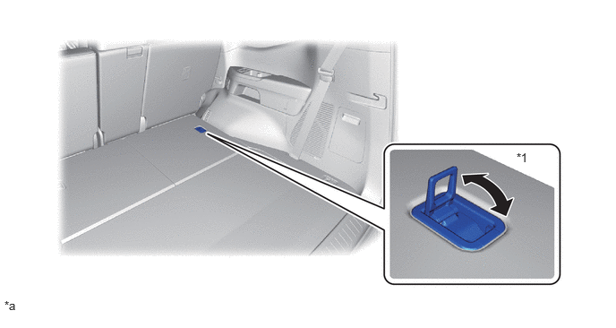
| *1 | Rope Hook Assembly | - | - |
| *a | The illustrations shown are examples only. | - | - |