JF2BM TRANSFER / 4WD / AWD FOUR WHEEL DRIVE CONTROL SYSTEM DETAILS CENTER DIFFERENTIAL
CONSTRUCTION
A torque-sensitive TORSEN LSD* is used in the center differential to generate differential limit force based on driving conditions and optimize torque distribution between the front/rear wheels. As a result, vehicle stability is enhanced when accelerating or driving at high-speeds, and turning performance is improved.
- HINT:
-
*: TORSEN is a registered trademark of JTEKT Corporation.
The TORSEN LSD is composed of a sun gear, a ring gear, 8 pinion gears, a planetary carrier and clutch plates . The sun gear is connected on the front wheel side, while the ring gear is connected on the rear wheel side.
Sliding the center differential lock sleeve engages with the spline along the outer circumference of the center differential case will switch to free-lock for the center differential case.
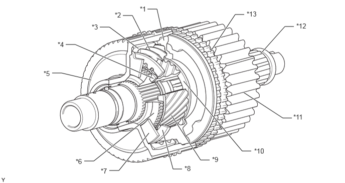
| *1 | Planetary Carrier | *2 | Pinion Gear |
| *3 | Ring Gear | *4 | No. 3 Clutch Plate |
| *5 | Center Differential Case | *6 | Coupling |
| *7 | No. 1 Clutch Plate | *8 | No. 2 Clutch Plate |
| *9 | Sun Gear | *10 | No. 4 Clutch Plate |
| *11 | Transfer Driven Sprocket | *12 | Rear Transfer Output Shaft |
| *13 | Transfer Front Drive Gear Piece | - | - |
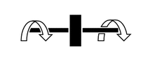
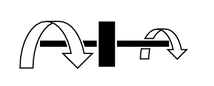
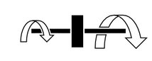
The torque distribution between the front/rear wheels changes based on driving conditions, as shown in the table below.
| Wheel Speed | Torque Distribution Ratio (Front:Rear) | |
|---|---|---|
| During Acceleration | During Deceleration | |
| Front wheel speed = rear wheel speed (when driving straight, etc.) | 41:59 | 41:59 |
|
||
| Front wheel speed > rear wheel speed (during turning, etc.) | 30:70 | 58:42 |
|
||
| Front wheel speed < rear wheel speed (during rear wheel slipping, etc.) | 53:47 | 29:71 |
|
||
OPERATION
LSD Operation Description
The TORSEN LSD generates differential limit force based on two operating principles: the operation of the clutch plate and the rotation resistance of the pinion gear. It lessens the difference in the rotational speed of the front/rear wheels and distributes torque from the high-speed side to the low-speed side
The operation of the clutch plate generates a difference in the rotation speed of the sun gear (front wheel) and ring gear (rear wheel). Differential limit force is generated when each gear is moved in the axial direction by spiral-shaped gear teeth and each clutch plate operates.
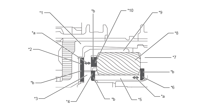
| *1 | Center Differential Case | *2 | No. 1 Clutch Plate |
| *3 | Coupling | *4 | No. 3 Clutch Plate |
| *5 | Sun Gear (Front Wheel Side) | *6 | No. 4 Clutch Plate |
| *7 | Planetary Carrier | *8 | Pinion Gear |
| *9 | Ring Gear (Rear Wheel Side) | *10 | No. 2 Clutch Plate |
| *a | Movement in Axial Direction due to Spiral-shaped Gear Teeth | *b | Generation of Differential Limit Force |
The rotational resistance of the pinion gear generates differential limit force when the pinion gear self-rotates due to the difference in rotational speed between the sun gear and ring gear, and the rotational resistance resulting from contact between the pinion gear and the wall surface of the planetary carrier holding the pinion gear functions as a force attempting to stop the self-rotation of the pinion gear.
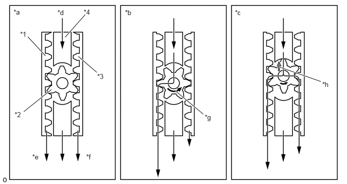
| *1 | Sun Gear (Front Wheel Side) | *2 | Pinion Gear |
| *3 | Ring Gear (Rear Wheel Side) | *4 | Planetary Carrier |
| *a | No Differential (When Driving Straight, etc.) | *b | Differential (During Turning, etc.) |
| *c | Differential Limit (During Turning, etc.) | *d | Input Speed |
| *e | Front Output Speed | *f | Rear Output Speed |
| *g | Self-rotation due to Difference in Rotational Speed | *h | Pinion Gear Comes Into Contact with Planetary Carrier (Limited Differential Torque is Produced) |
Operation when Front Wheel Speed = Rear Wheel Speed
No differential limit force is generated when there is no difference in rotational speed between the front/rear wheels (such as when driving straight). Torque will therefore be distributed between the front/rear wheels at a ratio of 41:59 (front:rear) due to the difference in radius of the sun gear and ring gear.
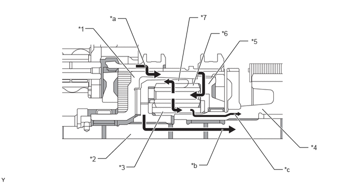
| *1 | Center Differential Case | *2 | Rear Transfer Output Shaft |
| *3 | Sun Gear (Front Wheel Side) | *4 | Transfer Drive Sprocket |
| *5 | Planetary Carrier | *6 | Pinion Gear |
| *7 | Ring Gear (Rear Wheel Side) | - | - |
| *a | Input Torque | *b | Rear Output Torque |
| *c | Front Output Torque | - | - |
Operation when Front Wheel Speed > Rear Wheel Speed
A differential limit force is generated by the difference in rotational speed between the sun gear and ring gear when the front wheel speed is high (such as during turning). As a result, the torque distribution to the front wheels will be reduced when accelerating during turning to suppress the front wheel skid tendency. Distribution will also change so as to suppress the front wheel speed versus input from the front wheels when decelerating during turning.
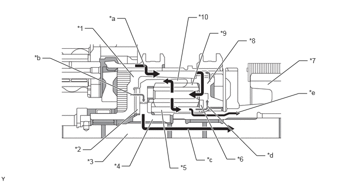
| *1 | Center Differential Case | *2 | No. 1 Clutch Plate |
| *3 | Rear Transfer Output Shaft | *4 | Coupling |
| *5 | Sun Gear (Front Wheel Side) | *6 | No. 4 Clutch Plate |
| *7 | Transfer Drive Sprocket | *8 | Planetary Carrier |
| *9 | Pinion Gear | *10 | Ring Gear (Rear Wheel Side) |
| *a | Input Torque | *b | Pushing on No. 1 Clutch Plate |
| *c | Rear Output Torque | *d | Pushing on No. 4 Clutch Plate |
| *e | Front Output Torque | - | - |
Operation when Front Wheel Speed < Rear Wheel Speed
A differential limit force is generated by the difference in rotational speed between the sun gear and ring gear when the rear wheel speed is high (such as during rear wheel slipping). As a result, the torque distribution to the rear wheels will be reduced when accelerating to suppress rear wheel slipping. Distribution will also change so as to suppress the rear wheel speed versus input from the rear wheels when decelerating.
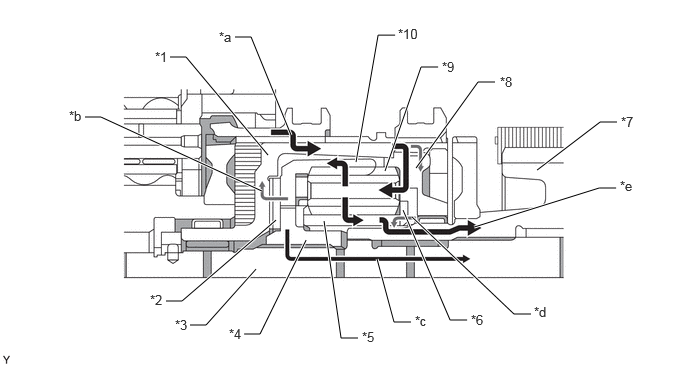
| *1 | Center Differential Case | *2 | No. 1 Clutch Plate |
| *3 | Rear Transfer Output Shaft | *4 | Coupling |
| *5 | Sun Gear (Front Wheel Side) | *6 | No. 4 Clutch Plate |
| *7 | Transfer Drive Sprocket | *8 | Planetary Carrier |
| *9 | Pinion Gear | *10 | Ring Gear (Rear Wheel Side) |
| *a | Input Torque | *b | Pushing on No. 1 Clutch Plate |
| *c | Rear Output Torque | *d | Pushing on No. 4 Clutch Plate |
| *e | Front Output Torque | - | - |
Free-lock Switching of Center Differential
The front drive clutch sleeve slides to the position where the center differential case and transfer front drive gear piece are engaged. The center differential becomes locked when the center differential case and transfer drive sprocket are connected.
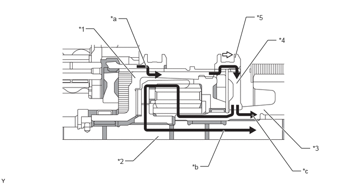
| *1 | Center Differential Case | *2 | Rear Transfer Output Shaft |
| *3 | Transfer Drive Sprocket | *4 | Transfer Front Drive Gear Piece |
| *5 | Front Drive Clutch Sleeve | - | - |
| *a | Input Torque | *b | Rear Output Torque |
| *c | Front Output Torque | - | - |