NM38G0E _52 Drivetrain _102376 AXLE AND DIFFERENTIAL _0473731 DIFFERENTIAL SYSTEM DE DETAILS F
AXLE AND DIFFERENTIAL DIFFERENTIAL SYSTEM DETAILS DIFFERENTIAL LOCK POSITION SWITCH
CONSTRUCTION
a.
Front Differential Lock (with Front Differential Lock Mechanism)
i.
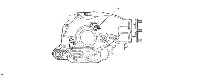
A No. 1 4 Wheel Drive Position Switch is provided.
3.615,0.906 4.167,0.385 true 4.208,0.25 4.521,0.406 0.313,0.156 10 false *1
| *1 | No. 1 4 Wheel Drive Position Switch | - | - |
ii.
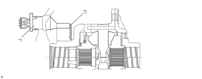
The No. 1 4 wheel drive position switch detects the operation status (free/lock) based on change in the voltage due to change in the differential lock position plate position.
2.51,0.885 2.958,0.469 true 0.771,1.313 1.219,0.896 true 0.656,1.344 0.969,1.5 0.313,0.156 10 false *1 2.948,0.333 3.26,0.49 0.313,0.156 10 false *2
| *1 | No. 1 4 Wheel Drive Position Switch | *2 | differential lock position plate |
b.
Rear Differential Lock
i.
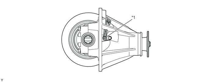
The differential lock indicator switch is positioned on the right side of the rear differential.
3.635,1.26 4.51,0.656 true 4.49,0.51 4.802,0.667 0.313,0.156 10 false *1
| *1 | Differential Lock Indicator Switch | - | - |
ii.
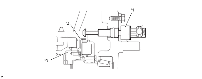
The differential lock indicator switch detects the rear differential position (free mode or lock mode) and is connected to the differential lock position plate, which is installed to the differential lock cam ring.
4.438,0.969 4.667,0.469 true 2.5,0.875 2.854,1.385 true 1.813,2.115 2.396,1.854 true 4.635,0.271 4.948,0.427 0.313,0.156 10 false *1 2.323,0.74 2.635,0.896 0.313,0.156 10 false *2 1.573,2.073 1.885,2.229 0.313,0.156 10 false *3
| *1 | Differential Lock Indicator Switch | *2 | Differential Lock Position Plate |
| *3 | Differential Lock Cam Ring | - | - |