V35A-FTS INTAKE / EXHAUST INTAKE SYSTEM GENERAL GENERAL
OUTLINE
A compact and lightweight resin silicon chip plug-in type intake mass air flow meter sub-assembly is used.
A turbocharger sub-assembly has been positioned at each bank by using a high efficiency and high output twin-turbo system.
A wastegate valve and an electric wastegate actuator are used for the turbocharger sub-assembly. When the vehicle is being driven at low load (supercharging not necessary), the back pressure and pumping loss are reduced during the exhaust stroke due to the wastegate valve opening. In addition, fine boost pressure control is made possible with the electric wastegate actuator.
A dedicated coolant path is provided for the turbocharger sub-assembly and intercooler assembly. A intercooler cooling radiator assembly is used in addition to the electric water pump assembly.
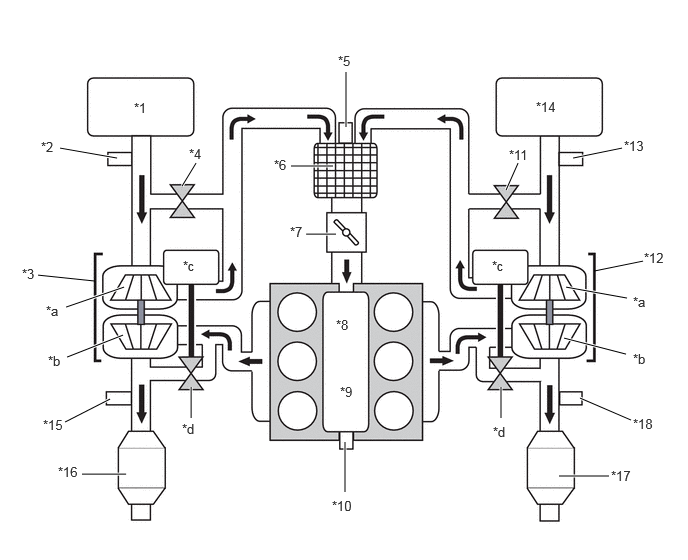
| *1 | Air Cleaner Assembly LH | *2 | Intake Air Mass Flow Meter Sub-assembly (Bank 2) |
| *3 | No. 1 Turbocharger Sub-assembly | *4 | Air By-pass Valve Assembly (Bank 2) |
| *5 | No. 1 Turbo Pressure Sensor (Bank 2) | *6 | Intercooler Assembly |
| *7 | Throttle Body with Motor Assembly | *8 | Intake Air Surge Tank |
| *9 | Intake Manifold | *10 | No. 3 Turbo Pressure Sensor |
| *11 | Air By-pass Valve Assembly (Bank 1) | *12 | No. 2 Turbocharger Sub-assembly |
| *13 | Intake Air Mass Flow Meter Sub-assembly (Bank 1) | *14 | Air Cleaner Assembly RH |
| *15 | Air Fuel Ratio Sensor (Bank 2 Sensor 1) | *16 | Converter Assembly LH |
| *17 | Converter Assembly RH | *18 | Air Fuel Ratio Sensor (Bank 1 Sensor 1) |
| *a | Compressor | *b | Turbine |
| *c | Wastegate Valve Actuator Assembly | *d | Wastegate Valve |
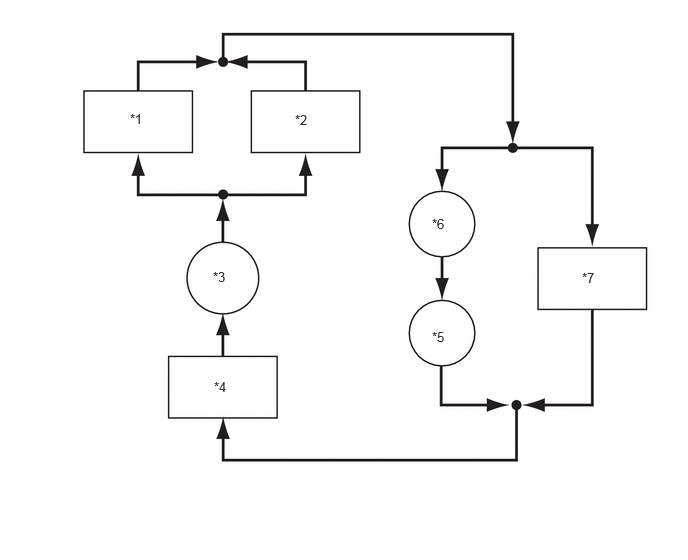
| *1 | Intercooler Cooling Radiator Assembly LH | *2 | Intercooler Cooling Radiator Assembly RH |
| *3 | Electric Water Pump Assembly | *4 | Radiator Reserve Tank Assembly |
| *5 | No. 1 Turbocharger Sub-assembly | *6 | No. 2 Turbocharger Sub-assembly |
| *7 | Intercooler Assembly | - | - |