NM38G0E _51 Engine / Hybrid System _101631 V35A-FTS INTAKE / EXHAUST _0473858 EXHAUST SYSTEM GE GENERAL F
V35A-FTS INTAKE / EXHAUST EXHAUST SYSTEM GENERAL GENERAL
OUTLINE
a.
A stainless steel converter assembly, front exhaust pipe assembly, center exhaust pipe assembly and exhaust tail pipe assembly are used.
b.
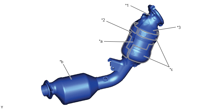
The placement of the catalyst is adjusted so that exhaust gas from the wastegate port on the turbocharger makes direct contact with the catalyst, in order to accelerate catalyst warm-up and reduce emissions.
c.
The No. 1 catalyst and No. 2 catalyst are located in the converter assembly, allowing the No. 2 catalyst to be placed close to the engine in order to reduce emissions.
d.
An insulator with a damping mat structure and an outer sheet covering the entire No. 1 catalyst is used as a structure to reduce characteristic turbo noise.
5.25,0.531 4.563,0.198 true 4.604,1.135 3.719,0.74 true 4.656,1.469 3.635,1.448 true 5.021,1.958 5.917,2.344 5.917,2.344 5.448,1.344 true 2.5,2.781 2.208,2.24 true 6.146,0.948 5.344,1.073 true 4.375,0.104 4.688,0.302 0.313,0.198 10 false *1 3.542,0.615 3.854,0.813 0.313,0.198 10 false *2 3.458,1.354 3.771,1.552 0.313,0.198 10 false *a 5.927,2.344 6.24,2.542 0.313,0.198 10 false *c 2.083,2.073 2.396,2.271 0.313,0.198 10 false *b 6.188,0.875 6.5,1.073 0.313,0.198 10 false *3
| *1 | Converter Assembly with Catalyst | *2 | Upper Exhaust Manifold Heat Insulator |
| *3 | Lower Exhaust Manifold Heat Insulator | - | - |
| *a | No. 1 Catalyst | *b | No. 2 Catalyst |
| *c | Damping Mat Structure | - | - |