STEERING COLUMN STEERING COLUMN SYSTEM DETAILS ENERGY ABSORBING MECHANISM
CONSTRUCTION
Models with Power Tilt and Power Telescopic Steering Column
A tube type energy absorbing mechanism, which has a retracting double-channel tube, is used.
The No. 2 steering intermediate shaft assembly retracts to absorb the impact from the rack and pinion power steering gear assembly (primary collision).
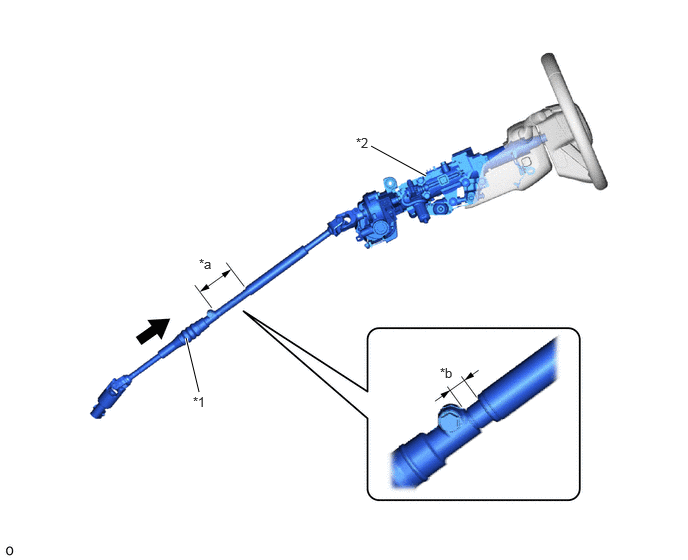
| *1 | No. 2 Steering Intermediate Shaft Assembly | *2 | Electric Power Steering Column Sub-assembly |
| *a | Before Collision | *b | After Collision |

|
Contract | - | - |
The impact from the steering wheel assembly (secondary collision) is absorbed by the retraction of the double-channel structure tube of the steering column assembly The tube area of the steering column assembly disengages during a collision, the column tube retracts and the steering wheel assembly moves towards the front of the vehicle. Also, the load during disengagement is optimally controlled due to the friction force of the tolerance ring.
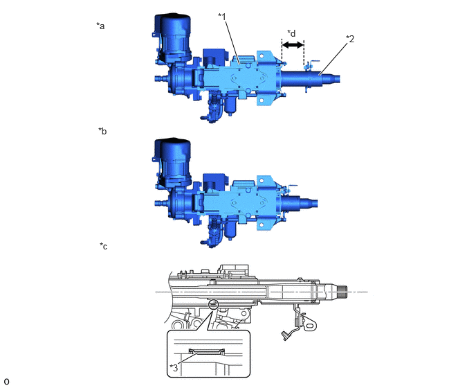
| *1 | Electric Power Steering Column Sub-assembly | *2 | Column Tube |
| *3 | Tolerance Ring | - | - |
| *a | Before Collision | *b | After Collision |
| *c | Column Tube Cross Section | *d | Sliding Stroke |
Models with Manual Tilt and Manual Telescopic Steering Column
The No. 2 steering intermediate shaft assembly contracts during a primary collision (vehicle to another object) to reduce the possibility of the steering column assembly and the steering wheel assembly protruding further into the cabin.
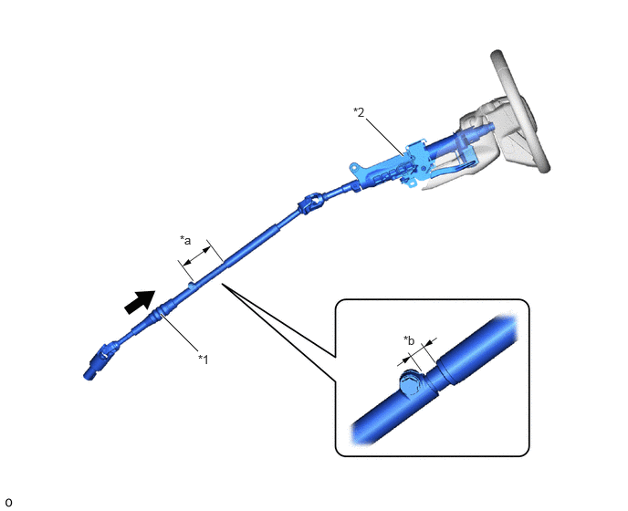
| *1 | No. 2 Steering Intermediate Shaft Assembly | *2 | Steering Column Assembly |
| *a | Before Collision | *b | After Collision |
|
|
Contract | - | - |
The steering column assembly contracts during a secondary collision (driver and vehicle) in order to absorb impact. The breakaway pin on the housing shears to move the steering wheel assembly toward the front of the vehicle. As the steering column assembly contracts, the column tube slides on the inner surface of the housing, generating friction and absorbing the energy of the collision.
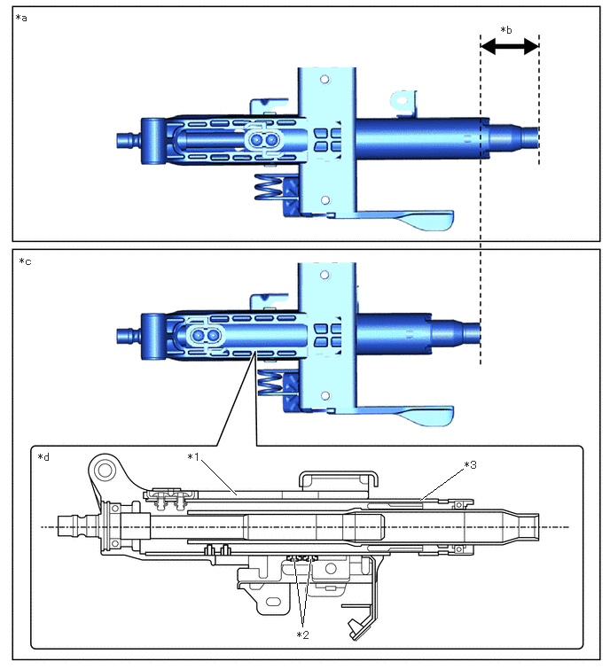
| *1 | Housing | *2 | Breakaway Pin |
| *3 | Column Tube | - | - |
| *a | Before Collision | *b | Sliding Stroke |
| *c | After Collision | *d | Cross Section |