V35A-FTS ENGINE CONTROL SFI SYSTEM DETAILS KNOCK CONTROL SENSOR
CONSTRUCTION
A flat type knock control sensor (non-resonant type) is used.
A flat type knock control sensor (non-resonant type) has the ability to detect vibrations in a wider frequency band (from approximately 5 kHz to 15 kHz). The sensor has the following features:
The engine knocking frequency will vary slightly depending on the engine speed. The flat type knock control sensor can detect vibrations even when the engine knocking frequency changes. Due to the use of the flat type knock control sensor, the vibration detection ability has been increased compared to a conventional type knock control sensor, and more precise ignition timing control is possible.
A flat type knock control sensor is installed in an engine by placing it over the stud bolt installed on the cylinder block sub-assembly. For this reason, a hole for the stud bolt exists in the center of the sensor.
In the sensor, a steel weight is located in the upper portion. An insulator is located between the weight and the piezoelectric element.
An open/short circuit detection resistor is integrated in the sensor. When the engine switch is on (IG), the open/short circuit detection resistor in the knock control sensor and the resistor in the ECM keep the voltage at terminal KNK1 constant. An Integrated Circuit (IC) in the ECM constantly monitors the voltage of terminal KNK1. If the open/short circuit occurs between the knock control sensor and the ECM, the voltage of terminal KNK1 will change and the ECM will detect the open/ short circuit and store a Diagnostic Trouble Code (DTC).
Vibrations caused by knocking are transmitted to the steel weight. The inertia of this weight applies pressure to the piezoelectric element. This action generates electromotive force.
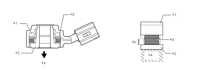
| *1 | Steel Weight | *2 | Base |
| *3 | Piezoelectric Element | *4 | Cylinder Block Sub-assembly |
| *a | Cylinder Block Sub-assembly Side | *b | Stress due to Vibrations in Cylinder Block Sub-assembly |