Home › Engine / Hybrid System › V35A-FTS (ENGINE CONTROL) › SFI SYSTEM
NM38G0E _51 Engine / Hybrid System _101627 V35A-FTS ENGINE CONTROL _0478156 SFI SYSTEM DE DETAILS F

V35A-FTS ENGINE CONTROL  SFI SYSTEM  DETAILS  AIR FUEL RATIO SENSOR  


CONSTRUCTION


a.

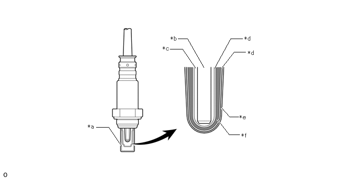
The basic construction of the air fuel ratio sensor (sensor 1) and the air fuel ratio sensor (sensor 2) is the same. However, they are divided into the cup type and the planar type, in accordance with the different types of heater construction that are used.


b.

The air fuel ratio sensor (sensor 1) is located upstream of the three-way catalyst in the converter assembly, and the air fuel ratio sensor (sensor 2) is located downstream of the three-way catalyst in the converter assembly.


c.

The planar type air fuel ratio sensor (sensor 1) uses alumina, which excels in heat conductivity and insulation, to integrate a sensor element with the heater, thus achieving the excellent warm-up performance of the sensor.


d.

The cup type air fuel ratio sensor (sensor 2) contains a sensor element that surrounds the heater.
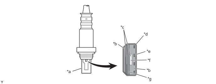
Air Fuel Ratio Sensor (Sensor 1) (Planar Type)
W148550C01
4.51,1.479 4.76,1.188 true 4.458,1.833 4.823,1.719 true 4.344,2.01 4.865,2 true 4.448,2.281 4.823,2.323 true 4.25,2.385 4.865,2.583 true 2.406,2.375 2.719,2.271 true 3.917,1.479 4.125,1.615 true 4.198,1.896 4.104,0.99 4.104,0.99 4.333,1.875 true 2.219,2.302 2.51,2.51 0.292,0.208 10 false *a 3.75,1.375 4.063,1.531 0.313,0.156 10 false *b 4,0.823 4.313,0.979 0.313,0.156 10 false *c 4.771,1.052 5.083,1.208 0.313,0.156 10 false *d 4.865,1.625 5.177,1.781 0.313,0.156 10 false *e 4.896,1.927 5.208,2.083 0.313,0.156 10 false *f 4.896,2.542 5.208,2.698 0.313,0.156 10 false *g 4.865,2.26 5.177,2.417 0.313,0.156 10 false *b
*a Cover *b Alumina
*c Platinum Electrode *d Coating (Ceramic)
*e Heater *f Atmosphere
*g Sensor Element (Zirconia) - -


Air Fuel Ratio Sensor (Sensor 2) (Cup Type)
W134455C01
2.021,2.677 2.281,2.677 2.281,2.677 2.552,3.073 true 4.656,1.427 4.917,1.094 4.917,1.094 5.156,1.094 true 4.51,1.427 4.844,0.813 4.844,0.813 5.094,0.813 true 3.74,0.813 3.938,0.813 3.938,0.813 4.281,1.417 true 3.573,1.031 3.833,1.031 3.833,1.031 4.104,1.427 true 4.646,2.26 4.823,2.458 4.823,2.458 5.01,2.458 true 4.563,2.51 4.813,2.833 4.813,2.833 5.031,2.833 true 1.844,2.594 2.156,2.75 0.313,0.156 10 false *a 3.583,0.74 3.896,0.896 0.313,0.156 10 false *b 3.417,0.948 3.729,1.104 0.313,0.156 10 false *c 5.135,0.74 5.448,0.896 0.313,0.156 10 false *d 5.031,2.396 5.344,2.552 0.313,0.156 10 false *e 5.073,2.781 5.385,2.938 0.313,0.156 10 false *f 5.208,1.042 5.521,1.198 0.313,0.156 10 false *d
*a Cover *b Heater
*c Atmosphere *d Platinum Electrode
*e Coating (Ceramic) *f Sensor Element (Zirconia)


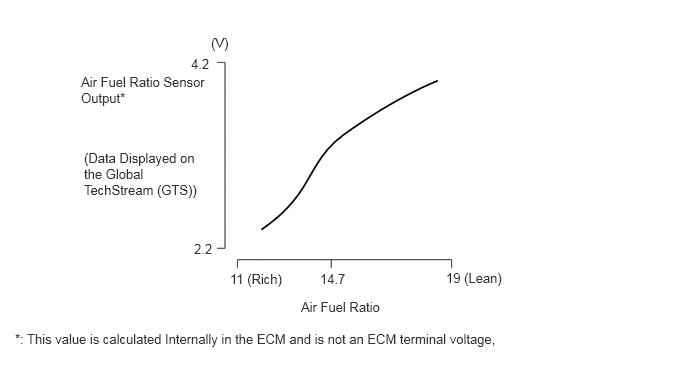
Output Characteristics of The Air Fuel Ratio Sensor (Sensor 1)
W134484E02
2.198,0.365 2.656,0.563 0.458,0.198 10 false (V) 1.99,0.583 2.448,0.781 0.458,0.198 10 false 4.2 2.021,2.51 2.479,2.708 0.458,0.198 10 false 2.2 0.875,1.563 2.083,2.531 1.208,0.969 10 false (Data Displayed on the Global TechStream (GTS)) 0.844,0.771 2.219,1.375 1.375,0.604 10 false Air Fuel Ratio Sensor Output* 0.156,3.448 6.656,3.729 6.5,0.281 10 false *: This value is calculated Internally in the ECM and is not an ECM terminal voltage, 4.646,2.813 5.375,3.115 0.729,0.302 10 false 19 (Lean) 3.333,2.823 3.656,3.104 0.323,0.281 10 false 14.7 2.396,2.823 3.125,3.125 0.729,0.302 10 false 11 (Rich) 3.135,3.115 4.083,3.385 0.948,0.271 10 false Air Fuel Ratio

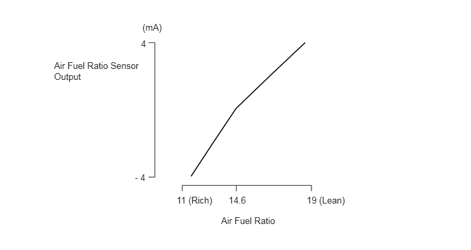
Output Characteristics of The Air Fuel Ratio Sensor (Sensor 2)
W134485E02
2.167,0.333 2.781,0.531 0.615,0.198 10 false (mA) 2.146,0.583 2.76,0.781 0.615,0.198 10 false 4 2.052,2.625 2.667,2.823 0.615,0.198 10 false - 4 0.823,0.917 2.198,1.677 1.375,0.76 10 false Air Fuel Ratio Sensor Output 2.688,2.969 3.302,3.167 0.615,0.198 10 false 11 (Rich) 4.667,2.969 5.281,3.167 0.615,0.198 10 false 19 (Lean) 3.479,2.969 3.979,3.24 0.5,0.271 10 false 14.6 3.365,3.281 4.281,3.583 0.917,0.302 10 false Air Fuel Ratio