V35A-FTS ENGINE MECHANICAL ENGINE UNIT DETAILS VALVE LASH ADJUSTER
CONSTRUCTION
The valve lash adjuster assembly, which is located at the fulcrum of the No. 1 valve rocker arm sub-assembly, consists primarily of a plunger, plunger spring, check ball and check ball spring.
The engine oil supplied by the cylinder head and the built-in spring actuates the valve lash adjuster assembly. The oil pressure and the spring force that act on the plunger push the No. 1 valve rocker arm sub-assembly against the cam, in order to adjust the valve clearance that is created during the opening and closing of the valve. As a result, engine noise has been reduced.
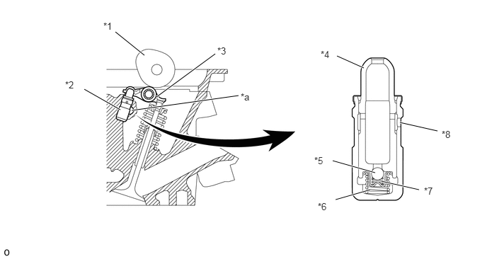
| *1 | Cam | *2 | Valve Lash Adjuster Assembly |
| *3 | Valve Rocker Arm Sub-assembly | *4 | Plunger |
| *5 | Check Ball | *6 | Plunger Spring |
| *7 | Check Ball Spring | *8 | Oil Hole |
| *a | Oil Passage | - | - |
OPERATION
When the camshaft revolves clockwise and the cam presses the valve rocker arm sub-assembly (applying), load is applied to both the valve and plunger. At this time, the plunger is pushed further downward, but the check ball is closed, stopping the plunger. Therefore, using the top of the plunger as a fulcrum, the valve rocker arm sub-assembly revolves in a clockwise direction and pushes the valve down.
When the cam moves past the high point, the valve rocker arm sub-assembly begins to move upward due to the force of the spring, but since that force is also applied to the valve lash adjuster assembly, oil pressure is maintained in the high-pressure chamber.
When the valve closes (application complete), the oil in the high-pressure chamber is released from its pressurized state. At this time, a valve clearance attempts to form. However, the plunger pushes the valve rocker arm sub-assembly upward due to the force of the spring and the valve clearance is maintained at 0. Simultaneously, since the volume in the high-pressure chamber grows, a difference in pressure occurs with the low-pressure chamber and the check ball spring force grows larger. When the check ball moves downward, an oil path is ensured and oil flows from the low-pressure chamber to the high-pressure chamber, preparing for the next operation (standby condition).
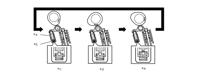
| *a | Low-pressure Chamber | *b | High-pressure Chamber |
| *c | Applying | *d | Finished Applying |
| *e | Standby Condition | - | - |