Home › Engine / Hybrid System › V35A-FTS (ENGINE MECHANICAL) › ENGINE UNIT
NM38G0E _51 Engine / Hybrid System _101628 V35A-FTS ENGINE MECHANICAL _0478157 ENGINE UNIT DE DETAILS F

V35A-FTS ENGINE MECHANICAL  ENGINE UNIT  DETAILS  VVT-i CONTROLLER  


CONSTRUCTION


a.

Intake Side

i.

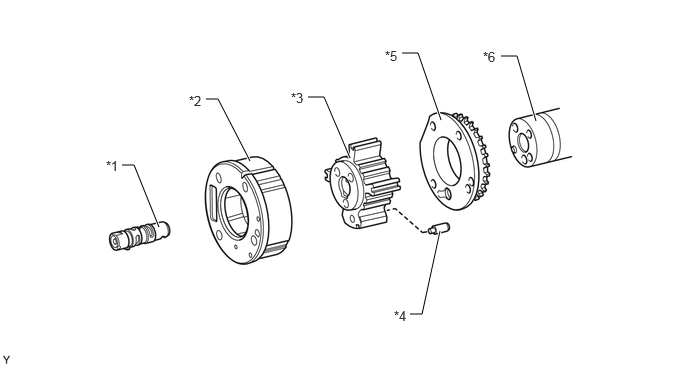
A 3-blade vane type VVT-i controller (camshaft timing intake gear assembly RH and camshaft timing intake gear assembly LH) is used on the intake side.


ii.

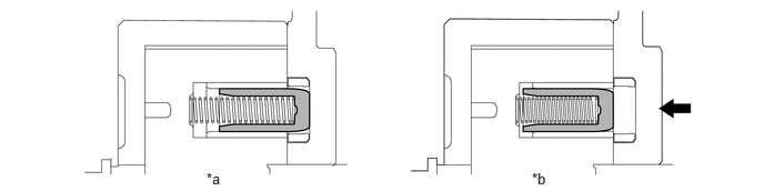
When the engine is stopped, a lock pin locks the intake camshaft at the most retarded position in order to enhance startability.
VVT-i Controller (Camshaft Timing Intake Gear Assembly)
W147481C01
0.958,2.042 1.125,2.042 1.125,2.042 1.375,2.542 true 1.792,1.302 1.958,1.302 1.958,1.302 2.271,1.813 true 2.917,1.042 3.083,1.042 3.083,1.042 3.417,1.656 true 3.302,0.521 3.469,0.521 3.469,0.521 3.885,1.271 true 4.229,3.125 4.396,3.125 4.396,3.125 4.563,2.292 true 5.302,2.75 5.469,2.75 5.469,2.75 5.635,1.781 true 0.76,1.979 0.99,2.146 0.229,0.167 10 false *1 1.594,1.24 1.823,1.406 0.229,0.167 10 false *2 2.74,0.979 2.969,1.146 0.229,0.167 10 false *3 3.135,0.458 3.365,0.625 0.229,0.167 10 false *4 4.063,3.063 4.313,3.229 0.25,0.167 10 false *5 5.125,2.688 5.354,2.854 0.229,0.167 10 false *6
*1 Camshaft Timing Oil Control Valve Assembly (Intake Camshaft Timing Gear Bolt Assembly) *2 Housing
*3 Vane (Fixed on Camshaft Sub-assembly No. 1 and Camshaft Sub-assembly No. 3) *4 Lock Pin
*5 Camshaft Timing Gear Cover RR (Sprocket) *6 Intake Camshaft Sub-assembly (Camshaft Sub-assembly No. 1 and Camshaft Sub-assembly No. 3)


Lock Pin
W145313C01
1.938,1.594 2.25,1.75 0.313,0.156 10 false *a 4.99,1.594 5.302,1.75 0.313,0.156 10 false *b
*a Lock Pin Connected *b Lock Pin Released
V100135

Oil Pressure - -


iii.

An oil control valve is built into the intake camshaft timing gear bolt assembly, which secures the vane to the intake camshaft (camshaft). As a result, the controlled oil passage is shortened to improve response performance and operation at low temperatures. The oil control valve switches the oil passage when pressed by the cam timing oil control solenoid assembly. Oil passage switching is controlled to continuously change the intake camshaft (camshaft) phase.
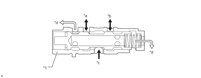
Camshaft Timing Oil Control Valve Assembly (Intake Camshaft Timing Gear Bolt Assembly)
W147497C01
1.708,2.406 1.854,2.406 1.854,2.406 2.042,1.854 true 1.542,2.354 1.854,2.51 0.313,0.156 10 false *1 2.979,0.479 3.292,0.635 0.313,0.156 10 false *a 3.833,0.49 4.146,0.646 0.313,0.156 10 false *b 3.438,2.167 3.75,2.323 0.313,0.156 10 false *c 1.938,0.729 2.156,0.99 0.219,0.26 10 false *d 5.333,1.792 5.646,1.948 0.313,0.156 10 false *d
*1 Camshaft Timing Oil Control Valve Assembly (Intake Camshaft Timing Gear Bolt Assembly) - -
*a To Retard Side Vane Chamber *b To Advance Side Vane Chamber
*c Engine Oil *d Drain


b.

Exhaust Side

i.

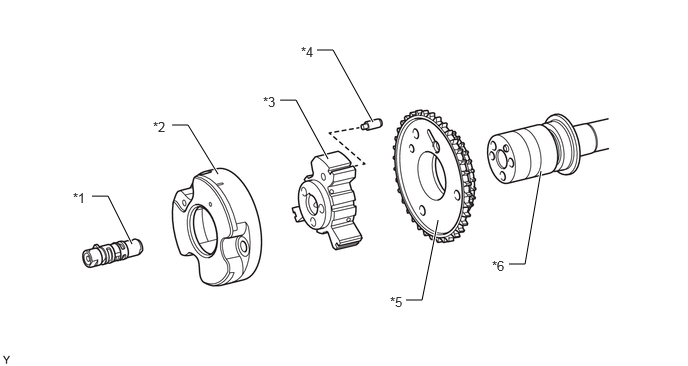
A 3-blade vane type VVT-i controller (camshaft timing exhaust gear assembly RH and camshaft timing exhaust gear assembly LH) is used on the exhaust side.


ii.

When the engine is stopped, a lock pin locks the exhaust camshaft at the most advanced position in order to enhance startability.


iii.

An advance assist spring is provided in the VVT-i controller (camshaft timing exhaust gear assembly RH) to assist the necessary torque in the advanced direction to keep the lock pin securely connected when the engine is stopped.
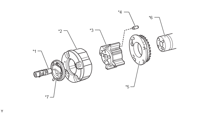
VVT-i Controller (Camshaft Timing Exhaust Gear Assembly RH)
W148516C02
1.271,1.719 1.396,1.719 1.396,1.719 1.656,2.365 true 2.146,1.031 2.271,1.031 2.271,1.031 2.604,1.677 true 3.208,1.01 3.375,1.01 3.375,1.01 3.646,1.646 true 4.406,2.927 4.531,2.927 4.531,2.927 4.719,2.063 true 4.188,0.406 4.354,0.406 4.354,0.406 4.583,0.917 true 5.219,0.583 5.385,0.583 5.385,0.583 5.583,1.26 true 1.688,3.281 1.813,3.281 1.813,3.281 1.906,2.625 true 1.104,1.646 1.333,1.813 0.229,0.167 10 false *1 1.969,0.969 2.188,1.188 0.219,0.219 10 false *2 3.031,0.938 3.292,1.094 0.26,0.156 10 false *3 3.99,0.323 4.24,0.49 0.25,0.167 10 false *4 4.24,2.844 4.479,3.01 0.24,0.167 10 false *5 5.031,0.51 5.281,0.677 0.25,0.167 10 false *6 1.521,3.188 1.771,3.354 0.25,0.167 10 false *7
*1 Camshaft Timing Oil Control Valve Assembly (Exhaust Camshaft Timing Gear Bolt Assembly) *2 Housing
*3 Vane (Fixed on Camshaft Sub-assembly No. 2) *4 Lock Pin
*5 Camshaft Timing Gear Cover RR (Sprocket) *6 Exhaust Camshaft Sub-assembly (Camshaft Sub-assembly No. 2)
*7 Assist Spring - -


VVT-i Controller (Camshaft Timing Exhaust Gear Assembly LH)
W147491C01
1.271,1.719 1.396,1.719 1.396,1.719 1.656,2.365 true 2.146,1.031 2.271,1.031 2.271,1.031 2.604,1.677 true 3.208,1.01 3.375,1.01 3.375,1.01 3.646,1.646 true 4.271,3.271 4.396,3.271 4.396,3.271 4.583,2.406 true 4.188,0.552 4.354,0.552 4.354,0.552 4.594,1.25 true 5.219,0.583 5.385,0.583 5.385,0.583 5.583,1.26 true 1.104,1.646 1.333,1.813 0.229,0.167 10 false *1 1.969,0.969 2.188,1.188 0.219,0.219 10 false *2 3.031,0.938 3.292,1.094 0.26,0.156 10 false *3 4.104,3.208 4.354,3.375 0.25,0.167 10 false *4 4.01,0.5 4.25,0.667 0.24,0.167 10 false *5 5.031,0.51 5.281,0.677 0.25,0.167 10 false *6
*1 Camshaft Timing Oil Control Valve Assembly (Exhaust Camshaft Timing Gear Bolt Assembly) *2 Housing
*3 Vane (Fixed on Camshaft Sub-assembly No. 4) *4 Lock Pin
*5 Camshaft Timing Gear Cover RR (Sprocket) *6 Exhaust Camshaft Sub-assembly (Camshaft Sub-assembly No. 4)


Lock Pin
W145313C01
1.938,1.594 2.25,1.75 0.313,0.156 10 false *a 4.99,1.594 5.302,1.75 0.313,0.156 10 false *b
*a Lock Pin Connected *b Lock Pin Released
V100135

Oil Pressure - -


iv.

An oil control valve is built into the exhaust camshaft timing gear bolt assembly, which secures the vane to the exhaust camshaft (camshaft). As a result, the controlled oil passage is shortened to improve response performance and operation at low temperatures. The oil control valve switches the oil passage when pressed by the cam timing oil control solenoid assembly. Oil passage switching is controlled to continuously change the exhaust camshaft (camshaft) phase.

Camshaft Timing Oil Control Valve Assembly (Exhaust Camshaft Timing Gear Bolt Assembly)
W147497C01
1.708,2.406 1.854,2.406 1.854,2.406 2.042,1.854 true 1.542,2.354 1.854,2.51 0.313,0.156 10 false *1 2.979,0.479 3.292,0.635 0.313,0.156 10 false *a 3.833,0.49 4.146,0.646 0.313,0.156 10 false *b 3.438,2.167 3.75,2.323 0.313,0.156 10 false *c 1.938,0.729 2.156,0.99 0.219,0.26 10 false *d 5.333,1.792 5.646,1.948 0.313,0.156 10 false *d
*1 Camshaft Timing Oil Control Valve Assembly (Exhaust Camshaft Timing Gear Bolt Assembly) - -
*a To Advance Side Vane Chamber *b To Retard Side Vane Chamber
*c Engine Oil *d Drain


OPERATION


a.

Advance

i.

The cam timing oil control solenoid assembly operates according to the advance signal from the ECM. When the oil control valve reaches the position shown in the following illustration, the advance side vane chamber of the VVT-i controller (camshaft timing gear assembly) is affected by oil pressure and the vane inside the VVT-i controller (camshaft timing gear assembly) rotates in the advanced direction. The intake camshaft (camshaft) fixed to the vane also rotates to the advanced side.
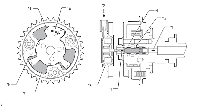
Intake Side
W147498C01
1.188,0.302 1.354,0.302 1.354,0.302 1.688,1.052 true 2.365,0.271 2.198,0.271 2.198,0.271 1.948,1.104 true 0.406,3.021 0.573,3.021 0.573,3.021 1.031,2.073 true 0.99,3.313 1.24,3.313 1.24,3.313 1.49,2.563 true 3.313,3.031 3.479,3.031 3.479,3.031 3.76,2.313 true 5.448,1.792 5.865,0.958 5.865,0.958 6.031,0.958 true 4.885,1.604 5.583,0.635 5.583,0.635 5.75,0.635 true 4.594,1.583 5.313,0.365 5.313,0.365 5.479,0.365 true 4.042,3.156 4.208,3.156 4.208,3.156 4.344,1.813 true 0.99,0.229 1.24,0.396 0.25,0.167 10 false *1 3.625,0.115 3.854,0.271 0.229,0.156 10 false *2 3.135,2.969 3.385,3.135 0.25,0.167 10 false *3 2.396,0.208 2.708,0.365 0.313,0.156 10 false *a 0.24,2.938 0.469,3.104 0.229,0.167 10 false *b 0.802,3.229 1.115,3.385 0.313,0.156 10 false *c 5.5,0.302 5.813,0.458 0.313,0.156 10 false *d 5.781,0.573 6.094,0.729 0.313,0.156 10 false *e 6.073,0.896 6.385,1.052 0.313,0.156 10 false *f 3.896,3.094 4.208,3.25 0.313,0.156 10 false *f
*1 Vane *2 ECM
*3 Cam Timing Oil Control Solenoid Assembly - -
*a Rotation Direction *b Retard Side Vane Chamber
*c Advance Side Vane Chamber *d From Retard Side Vane Chamber
*e To Advance Side Vane Chamber *f Drain


ii.

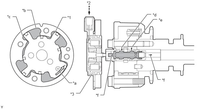
The cam timing oil control solenoid assembly operates according to the advance signal from the ECM. When the oil control valve reaches the position shown in the following illustration, the advance side vane chamber of the VVT-i controller (camshaft timing exhaust gear assembly) is affected by oil pressure and the vane inside the VVT-i controller (camshaft timing exhaust gear assembly) rotates in the advanced direction. The exhaust camshaft (camshaft) fixed to the vane also rotates to the advanced side.
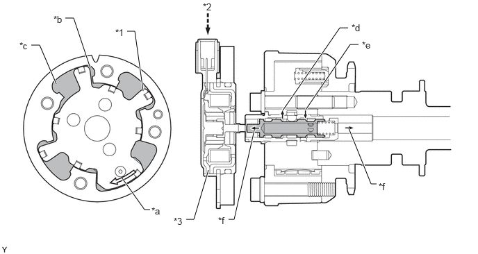
Exhaust Side
W147499C01
1.906,0.469 2.021,0.469 2.021,0.469 2.146,1.365 true 0.979,0.271 1.104,0.271 1.104,0.271 1.354,1.021 true 0.469,0.677 0.594,0.677 0.594,0.677 0.844,1.26 true 2.25,3.146 2.167,3.146 2.167,3.146 1.833,2.677 true 2.792,3.292 2.906,3.292 2.906,3.292 3.125,2.552 true 3.427,3.292 3.51,3.292 3.51,3.292 3.813,1.948 true 5.646,2.76 5.563,2.76 5.563,2.76 5.229,1.927 true 5.375,0.667 5.25,0.667 5.25,0.667 4.583,1.646 true 5.219,0.417 5.094,0.417 5.094,0.417 4.24,1.656 true 1.729,0.406 1.979,0.563 0.25,0.156 10 false *1 3.042,0.021 3.208,0.188 0.167,0.167 10 false *2 2.604,3.24 2.833,3.406 0.229,0.167 10 false *3 3.271,3.229 3.438,3.427 0.167,0.198 10 false *f 2.271,3.083 2.49,3.25 0.219,0.167 10 false *a 0.802,0.208 1.031,0.365 0.229,0.156 10 false *b 0.292,0.604 0.521,0.771 0.229,0.167 10 false *c 5.271,0.333 5.583,0.49 0.313,0.156 10 false *d 5.427,0.594 5.74,0.75 0.313,0.156 10 false *e 5.677,2.719 5.99,2.875 0.313,0.156 10 false *f
*1 Vane *2 ECM
*3 Cam Timing Oil Control Solenoid Assembly - -
*a Rotation Direction *b Retard Side Vane Chamber
*c Advance Side Vane Chamber *d To Advance Side Vane Chamber
*e From Retard Side Vane Chamber *f Drain


b.

Retard

i.

The cam timing oil control solenoid assembly operates according to the retard signal from the ECM. When the oil control valve reaches the position shown in the following illustration, the retard side vane chamber of the VVT-i controller (camshaft timing gear assembly) is affected by oil pressure and the vane inside the VVT-i controller (camshaft timing gear assembly) rotates in the retarded direction. The intake camshaft (camshaft) fixed to the vane also rotates to the retarded side.
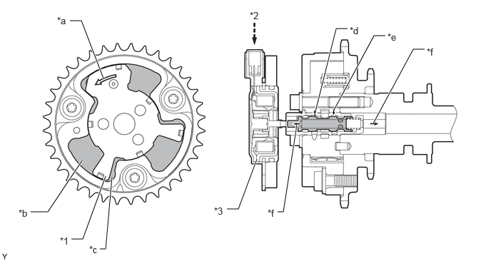
Intake Side
W147500C01
1.021,0.302 1.188,0.302 1.188,0.302 1.51,1.146 true 0.448,3.094 0.698,3.094 0.698,3.094 1.198,2.344 true 1.042,3.49 1.208,3.49 1.208,3.49 1.542,2.573 true 1.458,3.635 1.542,3.635 1.542,3.635 1.635,2.583 true 3.313,3.052 3.479,3.052 3.479,3.052 3.75,2.323 true 4.052,3.094 4.135,3.094 4.135,3.094 4.333,1.823 true 4.875,1.604 5.458,0.521 5.458,0.521 5.625,0.521 true 4.604,1.625 4.906,0.417 4.906,0.417 5.073,0.417 true 5.448,1.802 6.031,0.719 6.031,0.719 6.198,0.719 true 0.875,3.438 1.135,3.604 0.26,0.167 10 false *1 3.646,0.146 3.958,0.302 0.313,0.156 10 false *2 3.125,3 3.438,3.156 0.313,0.156 10 false *3 0.833,0.219 1.146,0.375 0.313,0.156 10 false *a 0.271,3.031 0.583,3.188 0.313,0.156 10 false *b 1.302,3.563 1.615,3.719 0.313,0.156 10 false *c 5.104,0.365 5.417,0.521 0.313,0.156 10 false *d 5.656,0.458 5.969,0.615 0.313,0.156 10 false *e 3.906,3.031 4.219,3.188 0.313,0.156 10 false *f 6.229,0.677 6.542,0.833 0.313,0.156 10 false *f
*1 Vane *2 ECM
*3 Cam Timing Oil Control Solenoid Assembly - -
*a Rotation Direction *b Retard Side Vane Chamber
*c Advance Side Vane Chamber *d To Retard Side Vane Chamber
*e From Advance Side Vane Chamber *f Drain


ii.

The cam timing oil control solenoid assembly operates according to the retard signal from the ECM. When the oil control valve reaches the position shown in the following illustration, the retard side vane chamber of the VVT-i controller (camshaft timing exhaust gear assembly) is affected by oil pressure and the vane inside the VVT-i controller (camshaft timing exhaust gear assembly) rotates in the retarded direction. The exhaust camshaft (camshaft) fixed to the vane also rotates to the retarded side.
Exhaust Side
W147501C01
2.313,0.604 2.177,0.604 2.177,0.604 1.896,1.167 true 0.938,0.354 1.094,0.354 1.094,0.354 1.26,1.021 true 0.438,0.583 0.563,0.583 0.563,0.583 0.802,1.292 true 2.51,2.896 2.406,2.896 2.406,2.896 2.063,2.49 true 2.646,3.26 2.781,3.26 2.781,3.26 3.208,2.573 true 3.49,3.323 3.615,3.323 3.615,3.323 3.885,1.927 true 5.469,0.677 5.333,0.677 5.333,0.677 4.583,1.656 true 5.594,2.781 5.49,2.781 5.49,2.781 5.229,1.927 true 5.26,0.5 5.125,0.5 5.125,0.5 4.24,1.646 true 2.344,0.531 2.604,0.698 0.26,0.167 10 false *1 3.021,0.021 3.25,0.188 0.229,0.167 10 false *2 2.448,3.208 2.688,3.365 0.24,0.156 10 false *3 3.333,3.25 3.49,3.406 0.156,0.156 10 false *f 2.531,2.823 2.729,2.99 0.198,0.167 10 false *a 0.771,0.281 1.021,0.448 0.25,0.167 10 false *b 0.25,0.5 0.479,0.677 0.229,0.177 10 false *c 5.313,0.438 5.531,0.646 0.219,0.208 10 false *d 5.521,0.615 5.76,0.792 0.24,0.177 10 false *e 5.635,2.719 5.833,2.885 0.198,0.167 10 false *f
*1 Vane *2 ECM
*3 Cam Timing Oil Control Solenoid Assembly - -
*a Rotation Direction *b Retard Side Vane Chamber
*c Advance Side Vane Chamber *d From Advance Side Vane Chamber
*e To Retard Side Vane Chamber *f Drain


c.

Hold

i.

The ECM calculates the target advanced angle according to driving conditions and performs control. After setting the target timing, timings are maintained by the neutral oil control valve as long as driving conditions do not change. As a result, unnecessary engine oil discharge is suppressed while valve timings are aligned to the desired target position.