HEATING / AIR CONDITIONING AIR CONDITIONING SYSTEM DETAILS SERVO MOTOR
CONSTRUCTION
Air Conditioning Unit
The following damper servo motors are used.
|
·
Fresh / Recirculation Mode Door Switching Servo Motor
·
DEF Mode Door Switching Servo Motor
·
Driver Side FACE Mode Door Switching Servo Motor
·
Driver Side FOOT Mode Door and Inside-and-outside Dual Air Layer Switching Servo Motor
·
Front Passenger Side FACE Mode Door Switching Servo Motor
·
Front Passenger Side FOOT Mode Door and Inside-and-outside Dual Air Layer Switching Servo Motor
·
Rear Passenger Side Mode Door Switching Servo Motor
·
Driver Side Upper Layer Air Mix Servo Motor
·
Driver Side Lower Layer Air Mix Servo Motor
·
Front Passenger Side Upper Layer Air Mix Servo Motor
·
Front Passenger Side Lower Layer Air Mix Servo Motor
·
Rear passenger Left Side Air Mix Servo Motor
·
Rear passenger Right Side Air Mix Servo Motor |
|
·
Fresh / Recirculation Mode Door Switching Servo Motor
·
DEF Mode Door Switching Servo Motor
·
FACE Mode Door Switching Servo Motor
·
FOOT Mode Door and Inside-and-outside Dual Air Layer Switching Servo Motor
·
Rear Passenger Side Mode Door Switching Servo Motor
·
Driver Side Upper Layer Air Mix Servo Motor
·
Driver Side Lower Layer Air Mix Servo Motor
·
Front Passenger Side Upper Layer Air Mix Servo Motor
·
Front Passenger Side Lower Layer Air Mix Servo Motor |
A pulse pattern type servo motor that performs control by communicating with the air conditioning amplifier assembly over the bus lines is used for each servo motor. Along with using pulse pattern type servo motors, smart connectors contain ICs that have such functions as communicating with the air conditioning amplifier assembly.
The installation positions for the servo motors are on the side of the blower assembly for the fresh/recirculation damper servo motor, and on the side of the air conditioning unit for the air conditioning radiator damper servo sub-assembly.
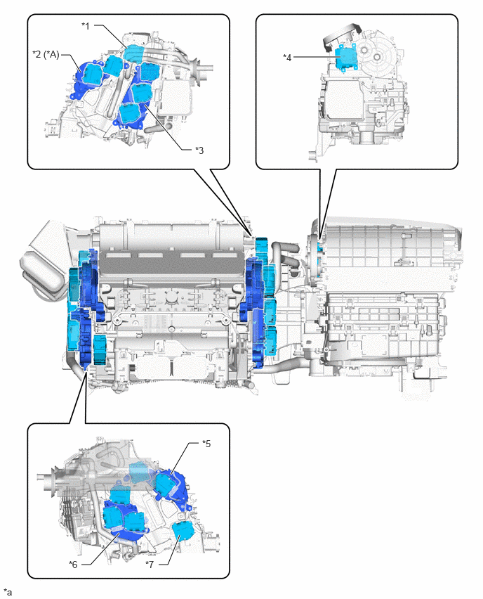
| *A | Models with Multi-Zone (4-Zone) Climate Control | - | - |
| *1 | No. 5 Air Conditioning Radiator Damper Servo Sub-assembly | *2 | No. 6 Air Conditioning Radiator Damper Servo Sub-assembly |
| *3 | No. 4 Air Conditioning Radiator Damper Servo Sub-assembly | *4 | No. 1 Blower Damper Servo Sub-assembly |
| *5 | No. 1 Air Conditioning Radiator Damper Servo Sub-assembly | *6 | No. 2 Air Conditioning Radiator Damper Servo Sub-assembly |
| *7 | No. 3 Air Conditioning Radiator Damper Servo Sub-assembly | - | - |
| *a | This illustration is an example only. | - | - |
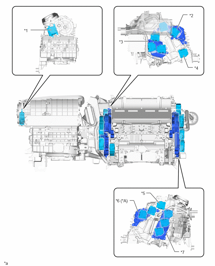
| *A | Models with Multi-Zone (4-Zone) Climate Control | - | - |
| *1 | No. 1 Blower Damper Servo Sub-assembly | *2 | No. 1 Air Conditioning Radiator Damper Servo Sub-assembly |
| *3 | No. 2 Air Conditioning Radiator Damper Servo Sub-assembly | *4 | No. 3 Air Conditioning Radiator Damper Servo Sub-assembly |
| *5 | No. 5 Air Conditioning Radiator Damper Servo Sub-assembly | *6 | No. 6 Air Conditioning Radiator Damper Servo Sub-assembly |
| *7 | No. 4 Air Conditioning Radiator Damper Servo Sub-assembly | - | - |
| *a | This illustration is an example only. | - | - |
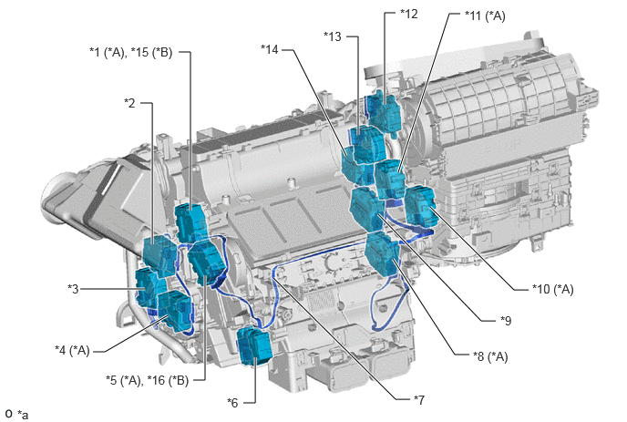
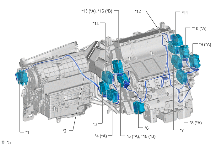
| *A | Models with Multi-Zone (4-Zone) Climate Control | *B | Models with Left and Right Independent Temperature Control |
| *1 | Driver Side FACE Mode Door Switching Servo Motor | *2 | Driver Side Upper Layer Air Mix Servo Motor |
| *3 | Driver Side Lower Layer Air Mix Servo Motor | *4 | Rear Passenger Left Side Air Mix Servo Motor |
| *5 | Driver Side FOOT Mode Door and Inside-and-outside Dual Air Layer Switching Servo Motor | *6 | Rear Passenger Side Mode Door Switching Servo Motor |
| *7 | Air Conditioning Harness Assembly | *8 | Rear Passenger Right Side Air Mix Servo Motor |
| *9 | Front Passenger Side Lower Layer Air Mix Servo Motor | *10 | Front Passenger Side FOOT Mode Door and Inside-and-outside Dual Air Layer Switching Servo Motor |
| *11 | Front Passenger Side FACE Mode Door Switching Servo Motor | *12 | Fresh / Recirculation Mode Door Switching Servo Motor |
| *13 | DEF Mode Door Switching Servo Motor | *14 | Front Passenger Side Upper Layer Air Mix Servo Motor |
| *15 | FACE Mode Door Switching Servo Motor | *16 | FOOT Mode Door and Inside-and-outside Dual Air Layer Switching Servo Motor |
| *a | This illustration is an example only. | - | - |
| *A | Models with Multi-Zone (4-Zone) Climate Control | *B | Models with Left and Right Independent Temperature Control |
| *1 | Fresh / Recirculation Mode Door Switching Servo Motor | *2 | Air Conditioning Harness Assembly |
| *3 | Front Passenger Side Lower Layer Air Mix Servo Motor | *4 | Rear Passenger Right Side Air Mix Servo Motor |
| *5 | Front Passenger Side FOOT Mode Door and Inside-and-outside Dual Air Layer Switching Servo Motor | *6 | Rear Passenger Side Mode Door Switching Servo Motor |
| *7 | Driver Side Lower Layer Air Mix Servo Motor | *8 | Rear Passenger Right Side Air Mix Servo Motor |
| *9 | Driver Side FOOT Mode Door and Inside-and-outside Dual Air Layer Switching Servo Motor | *10 | Driver Side FACE Mode Door Switching Servo Motor |
| *11 | DEF Mode Door Switching Servo Motor | *12 | Driver Side Upper Layer Air Mix Servo Motor |
| *13 | Front Passenger Side FACE Mode Door Switching Servo Motor | *14 | Front Passenger Side Upper Layer Air Mix Servo Motor |
| *15 | FOOT Mode Door and Inside-and-outside Dual Air Layer Switching Servo Motor | *16 | FACE Mode Door Switching Servo Motor |
| *a | This illustration is an example only. | - | - |
Rear Air Conditioning Unit (Models with Rear Air Conditioning Unit)
The following damper servo motors are used.
|
·
Rear Mode Door Switching Servo Motor
·
Rear Passenger Left Side Air Mix Servo Motor
·
Rear Passenger Right Side Air Mix Servo Motor |
A pulse pattern type servo motor that performs control by communicating with the air conditioning amplifier assembly over the bus lines is used for each servo motor. Along with using pulse pattern type servo motors, smart connectors contain ICs that have such functions as communicating with the air conditioning amplifier assembly.
The servo motors are installed of the rear air conditioning unit.
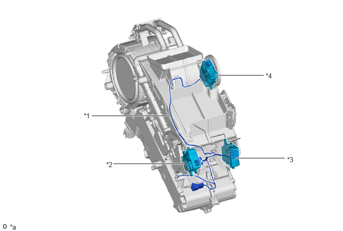
| *1 | No. 1 Cooler Wiring Harness Sub-assembly | *2 | Rear Airmix Damper Servo Sub-assembly
·
Rear Passenger Left Side Air Mix Servo Motor |
| *3 | No. 2 Airmix Damper Servo Sub-assembly
·
Rear Passenger Right Side Air Mix Servo Motor |
*4 | Rear Mode Damper Servo Sub-assembly
·
Rear Mode Door Switching Servo Motor |
| *a | This illustration is an example only. | - | - |
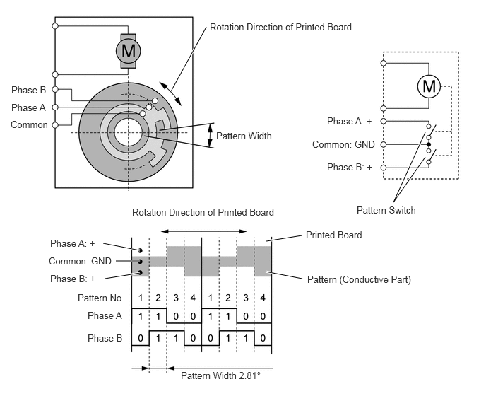
Pulse Pattern Type Servo Motor
In contrast to the previous type that detects the position by way of a potentiometer voltage, the pulse pattern type servo motor detects the relative position by way of the 2-bit on/off signals.
The forward and reverse revolutions of this motor are detected by way of 2 phases, A and B, which output 4 types of patterns. The air conditioning amplifier assembly counts the number of pulse patterns in order to determine the stopped position.