NM38G0E _58 Vehicle Interior _101133 HEATING / AIR CONDITIONING _0478955 AIR CONDITIONING SYSTEM DE DETAILS F
HEATING / AIR CONDITIONING AIR CONDITIONING SYSTEM DETAILS COOLER COMPRESSOR
CONSTRUCTION
a.
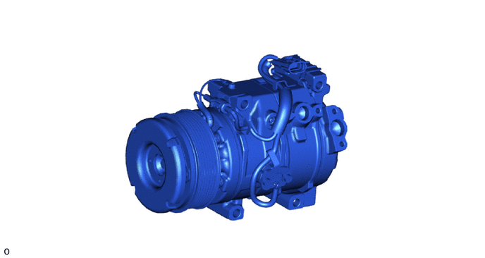
A fixed capacity swash plate type 10SR19 compressor is used.
b.
The lock sensor sends an compressor speed signal to the air conditioning amplifier assembly. The air conditioning amplifier assembly compares this signal with an engine speed signal sent from the ECM. If the air conditioning amplifier assembly determines that the compressor has locked, the air conditioning amplifier assembly turns the magnetic clutch off.
c.
Rotary Valve
i.
In order to reduce suction loss, the rotary valve has been replaced with a conventional suction valve.
ii.
The rotary valve is a hollow shaft, allowing refrigerant to be sucked directly into the cylinder bore through corresponding suction passages on the cylinder.
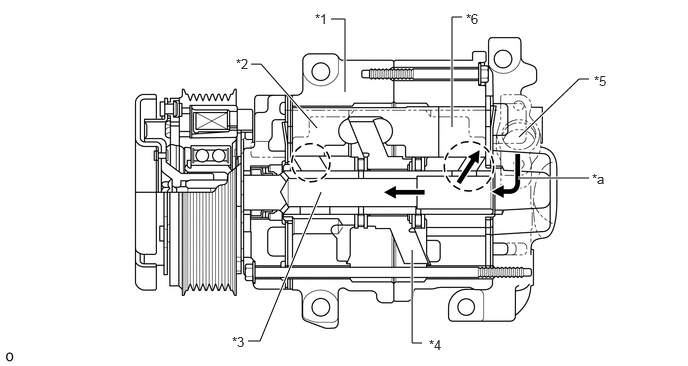
5.406,1.427 6.031,0.823 6.031,0.823 6.135,0.823 true 6.135,1.854 5.396,1.854 true 2.615,0.667 2.719,0.667 2.719,0.667 3.302,1.333 true 3.448,0.198 3.594,0.198 3.594,0.198 3.594,0.958 true 4.708,1.323 4.708,0.177 4.708,0.177 4.813,0.177 true 4.292,2.604 4.292,3.573 4.292,3.573 4.396,3.573 true 3.344,2 2.708,3.552 2.708,3.552 2.583,3.552 true 3.281,0.115 3.615,0.271 0.333,0.156 10 false *1 2.458,0.583 2.771,0.74 0.313,0.156 10 false *2 2.417,3.479 2.75,3.635 0.333,0.156 10 false *3 4.469,3.51 4.75,3.677 0.281,0.167 10 false *4 6.188,0.76 6.5,0.917 0.313,0.156 10 false *5 4.854,0.115 5.167,0.271 0.313,0.156 10 false *6 6.167,1.781 6.479,1.938 0.313,0.156 10 false *a
| *1 | Cylinder | *2 | Piston |
| *3 | Hollow Shaft | *4 | Swash Plate |
| *5 | Suction Section | *6 | Cylinder Bore |
| *a | Refrigerant Flow | - | - |
Image of Valve Operational Behavior During Suction
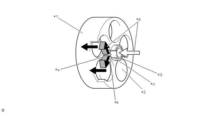
1.969,0.604 2.76,1.104 true 2.042,2.333 3.76,1.833 true 3.875,3.365 3.698,1.99 true 4.771,3 4.104,2.323 true 5.281,2.469 4.083,1.958 true 4.51,1.771 4.635,0.729 4.635,0.729 3.594,1.563 true 5.042,2.76 3.865,1.958 true 1.813,0.49 2.125,0.646 0.313,0.156 10 false *1 4.76,3.042 5.073,3.198 0.313,0.156 10 false *2 5.313,2.458 5.625,2.615 0.313,0.156 10 false *3 1.865,2.281 2.177,2.438 0.313,0.156 10 false *a 3.854,3.385 4.167,3.542 0.313,0.156 10 false *b 5.073,2.76 5.385,2.917 0.313,0.156 10 false *c 4.594,0.583 4.906,0.74 0.313,0.156 10 false *d
| *1 | Cylinder | *2 | Piston |
| *3 | Shaft | - | - |
| *a | Rotary Valve Intake | *b | Position where Rotary Valve Intake and Cylinder Intake Passage Align |
| *c | Cylinder Intake Passage | *d | Flow of Refrigerant |