NM38G0E _58 Vehicle Interior _101133 HEATING / AIR CONDITIONING _0478955 AIR CONDITIONING SYSTEM DE DETAILS F
HEATING / AIR CONDITIONING AIR CONDITIONING SYSTEM DETAILS REAR AIR CONDITIONING UNIT
CONSTRUCTION
a.
An rear cooling unit or rear air conditioning unit is provided depending on the model.
b.
A brushless motor that integrates a blower motor is used to save space.
c.
A cross-turn type evaporator is used.
d.
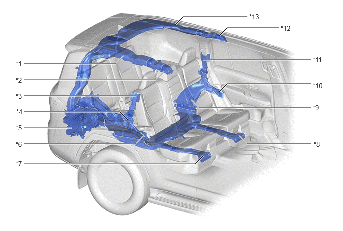
A register for blowing cool air out is provided for the rear roof sides and the upper portion of the package tray, improving rear seat comfort.
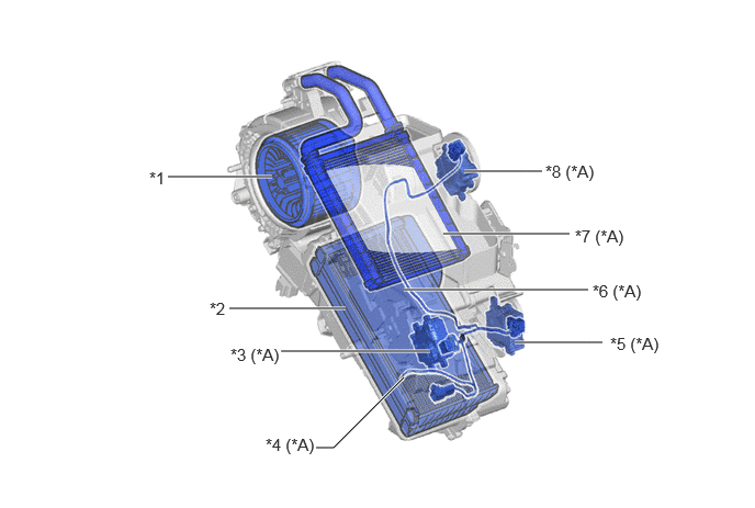
Air Conditioning Blower Assembly
4.885,3.25 5.563,3.25 5.563,3.25 5.719,3.25 true 4.406,1.625 4.99,1.625 4.99,1.625 5.146,1.625 true 4.208,2.219 5,2.219 5,2.219 5.406,2.219 true 1.594,1.677 2.583,1.677 true 2.177,2.927 3.281,2.927 true 3.833,2.75 4.667,2.75 4.667,2.75 5.583,2.75 true 2.667,3.333 3.833,3.333 3.833,3.333 4.083,3.333 true 3,4.25 3.167,4.25 3.167,4.25 3.833,3.583 true 1.417,1.594 1.76,1.813 0.344,0.219 11 false *1 1.99,2.833 2.333,3.052 0.344,0.219 11 false *2 2.188,3.271 2.833,3.5 0.646,0.229 11 false *3 (*A) 2.521,4.125 3.167,4.333 0.646,0.208 11 false *4 (*A) 5.792,3.167 6.417,3.406 0.625,0.24 11 false *5 (*A) 5.625,2.667 6.167,2.875 0.542,0.208 11 false *6 (*A) 5.458,2.146 6.031,2.385 0.573,0.24 11 false *7 (*A) 5.177,1.531 5.719,1.76 0.542,0.229 11 false *8 (*A)
| *A | Models with Rear Air Conditioning | - | - |
| *1 | Fan | *2 | Evaporator Sub-assembly (Rear) |
| *3 | Rear Airmix Damper Servo Sub-assembly | *4 | No. 2 Cooler Thermistor |
| *5 | No. 2 Airmix Damper Servo Sub-assembly | *6 | No. 2 Cooler Wiring Harness Sub-assembly |
| *7 | Heater Radiator Unit Sub-assembly | *8 | Rear Mode Damper Servo Sub-assembly |
5,2.833 5.167,3 5.167,3 6.5,3 true 4.583,0.75 4.75,0.583 4.75,0.583 5.833,0.583 true 4.25,1.25 6.333,1.25 6.333,1.25 6.5,1.25 true 0.5,1.333 2.417,1.333 2.417,1.333 2.583,1.167 true 0.5,1.667 3.25,1.667 3.25,1.667 3.417,1.5 true 0.5,2 2.667,2 2.667,2 2.833,2 true 0.5,2.667 0.958,2.667 0.958,2.667 1.5,2.667 true 0.5,3 2.833,3 2.833,3 3,2.833 true 0.5,3.417 4.083,3.417 4.083,3.417 4.25,3.25 true 4.583,1.917 4.75,1.75 4.75,1.75 6.5,1.75 true 3.667,0.521 3.833,0.354 3.833,0.354 5.167,0.354 true 4,2.083 4.167,2.25 4.167,2.25 6.5,2.25 true 0.5,2.333 2.5,2.333 2.5,2.333 2.667,2.5 true 0.333,1.25 0.646,1.406 0.313,0.156 10 false *1 0.333,1.594 0.646,1.75 0.313,0.156 10 false *2 0.333,1.927 0.667,2.083 0.333,0.156 10 false *3 0.344,2.25 0.833,2.854 0.49,0.604 10 false *4 0.333,2.583 0.667,3.083 0.333,0.5 10 false *5 0.333,3.333 0.646,3.49 0.313,0.156 10 false *7 6.552,2.927 7.156,3.104 0.604,0.177 10 false *8 6.531,1.708 7.156,1.917 0.625,0.208 10 false *10 6.531,1.167 7.156,1.458 0.625,0.292 10 false *11 5.865,0.51 7.156,0.74 1.292,0.229 10 false *12 5.208,0.271 7.156,0.51 1.948,0.24 10 false *13 0.333,2.927 0.667,3.083 0.333,0.156 10 false *6 6.531,2.167 7.156,2.375 0.625,0.208 10 false *9
| *1 | Roof Side Register Duct RH (to Rear No. 2 Seat Passenger) | *2 | Roof Side Register Duct RH (to Rear No. 1 Seat Passenger) |
| *3 | Piller Register Duct RH | *4 | Footwell Register Duct RH (to Rear No. 2 Seat Passenger) |
| *5 | Air Conditioning Blower Assembly | *6 | Quarter Trim Register Duct RH |
| *7 | Footwell Register Duct RH (to Rear No. 1 Seat Passenger) | *8 | Footwell Register Duct LH (to Rear No. 1 Seat Passenger) |
| *9 | Footwell Register Duct LH (to Rear No. 2 Seat Passenger) | *10 | Quarter Trim Register Duct LH |
| *11 | Piller Register Duct LH | *12 | Roof Side Register Duct LH (for Rear No. 1 Seat Passenger) |
| *13 | Roof Side Register Duct LH (for Rear No. 2 Seat Passenger) | - | - |
OPERATION
a.
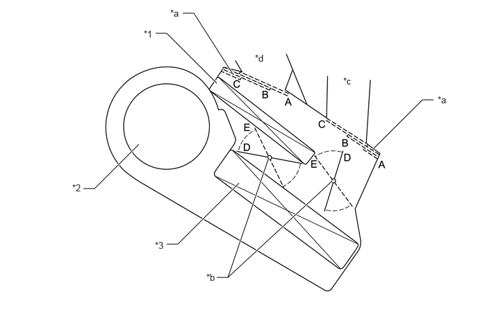
Mode Position and Damper Operation
5.583,2.25 6.333,1.5 6.333,1.5 6.5,1.5 true 2.333,0.5 2.5,0.5 2.5,0.5 3.25,1.25 true 1.25,2.833 1.417,2.833 1.417,2.833 2.083,2.167 true 2.5,3.667 2.667,3.667 2.667,3.667 3.583,2.75 true 2.74,0.198 2.906,0.198 2.906,0.198 3.479,1.094 true 4.979,2.719 3.417,4.167 3.417,4.167 4.031,2.365 true 3.25,4.167 3.417,4.167 false 2.156,0.427 2.469,0.625 0.313,0.198 10 false *1 1.083,2.74 1.396,2.938 0.313,0.198 10 false *2 2.323,3.604 2.635,3.802 0.313,0.198 10 false *3 2.552,0.115 2.865,0.313 0.313,0.198 10 false *a 3.094,4.083 3.406,4.281 0.313,0.198 10 false *b 6.563,1.417 6.875,1.615 0.313,0.198 10 false *a 5.146,1.135 5.458,1.333 0.313,0.198 10 false *c 3.823,0.792 4.135,0.99 0.313,0.198 10 false *d
| *1 | Heater Radiator Unit Sub-assembly | *2 | Fan |
| *3 | Rear Evaporator Sub-assembly | - | - |
| *a | Mode Control Damper | *b | Air Mix Control Damper |
| *c | to Roof Side Register | *d | to Piller Register, Quarter Trim Register, Footwell Duct |
| Control Damper | Operation Position | Damper Position | Operation | |
|---|---|---|---|---|
| Mode Control Damper |

|
FACE | A | Air blows out of the roof side register. |

|
BI-LEVEL | B | Air blows out of the roof side register and the footwell register. | |

|
FOOT | C | Air blows out of the footwell register. | |
| Air Mix Control Damper | MAX COLD to MAX HOT Temp. Setting | D-E | Varies the mixture ratio of the cold air and the hot air in order to regulate the temperature continuously from HOT to COLD. | |
b.
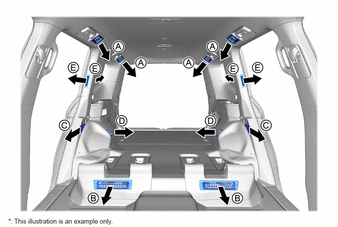
Air Outlets and Airflow Volume
0.177,4.615 6.292,4.813 6.115,0.198 10 false *: This illustration is an example only.
| Mode | A | B | C | D | E | |
|---|---|---|---|---|---|---|
|
|
FACE |

|

|
|
|
|
|
|
BI-LEVEL |

|

|
|
|
|
|
|
FOOT |
|
|

|
|
|