HEATING / AIR CONDITIONING AIR CONDITIONING SYSTEM DETAILS AIR CONDITIONING UNIT
CONSTRUCTION
An air conditioning unit that is compatible with left and right independent temperature control or multi-zone (4-ZONE) climate control is used.
The air conditioning unit consists of the No. 1 cooler evaporator sub-assembly, heater radiator unit sub-assembly, servo motors, evaporator temperature sensor (No. 1 cooler thermistor) and blower with fan motor sub-assembly.
A cross-turn type evaporator is used.
A Straight Flow Aluminum-II (SFA-II) heater core that is compact and offers advanced performance is used.
A pollen removing type clean air filter (air refiner element) is provided as standard equipment.
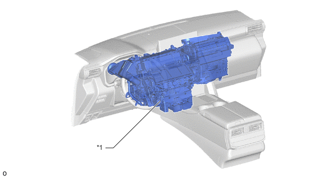
| *1 | Air Conditioning Unit | - | - |
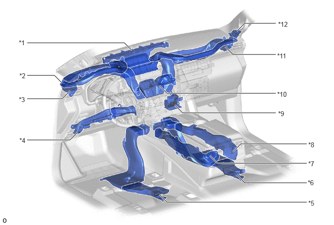
| *1 | Front Defroster Duct | *2 | Driver Side Side Defroster Duct |
| *3 | Driver Side Side Register Duct | *4 | Driver Side Footwell Duct |
| *5 | Rear Passenger Left Side Footwell Duct | *6 | Rear Passenger Right Side Footwell Duct |
| *7 | Rear Passenger Left Side Center Register Duct | *8 | Rear Passenger Right Side Center Register Duct |
| *9 | Front Passenger Side Footwell Duct | *10 | Center Register Duct |
| *11 | Front Passenger Side Side Register Duct | *12 | Front Passenger Side Side Defroster Duct |
OPERATION
Mode Position and Door Operation
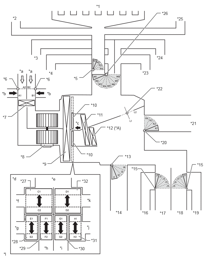
| *A | Models with PTC Heater | - | - |
| *1 | Front Defroster Duct | *2 | Side Defroster Duct LH |
| *3 | Side Register Duct LH | *4 | Center Register Duct LH |
| *5 | DEF Mode Door | *6 | Fresh / Recirculation Mode Door |
| *7 | Air Refiner Element (Clean Air Filter) | *8 | Blower Motor with Fan Sub-assembly |
| *9 | No. 1 Cooler Evaporator Sub-assembly | *10 | Air Mix Servo Motor |
| *11 | Heater Radiator Unit Sub-assembly | *12 | PTC Heater (Quick Heater Assembly) |
| *13 | FOOT Mode Door LH | *14 | Footwell Duct LH |
| *15 | Rear Passenger Mode Door | *16 | Rear Passenger Footwell Duct LH |
| *17 | Rear Passenger Register Duct LH | *18 | Rear Passenger Register Duct RH |
| *19 | Rear Passenger Footwell Duct RH | *20 | FOOT Mode Door RH |
| *21 | Footwell Duct RH | *22 | Inside-and-outside Dual Air Layer Door |
| *23 | Center Register Duct RH | *24 | Side Register Duct RH |
| *25 | Side Defroster Duct RH | *26 | FACE Mode Door Switching Servo Motor |
| *27 | Upper Layer Air Mix Door LH | *28 | Lower Layer Air Mix Door LH |
| *29 | Rear passenger Air Mix Door LH | *30 | Rear passenger Air Mix Door RH |
| *31 | Lower Layer Air Mix Door RH | *32 | Upper Layer Air Mix Door RH |
| *a | Recirculation Air | *b | Fresh Air |
| *c | [A] View | *d | Illustration Image View from [A] |
| *e | Defroster Duct | *f | Left Side Register Duct |
| *g | Left Side Footwell Duct | *h | Left Side Rear Duct |
| *i | Right Side Rear Duct | *j | Right Side Footwell Duct |
| *k | Right Side Register Duct | *l | This illustration is an image. |
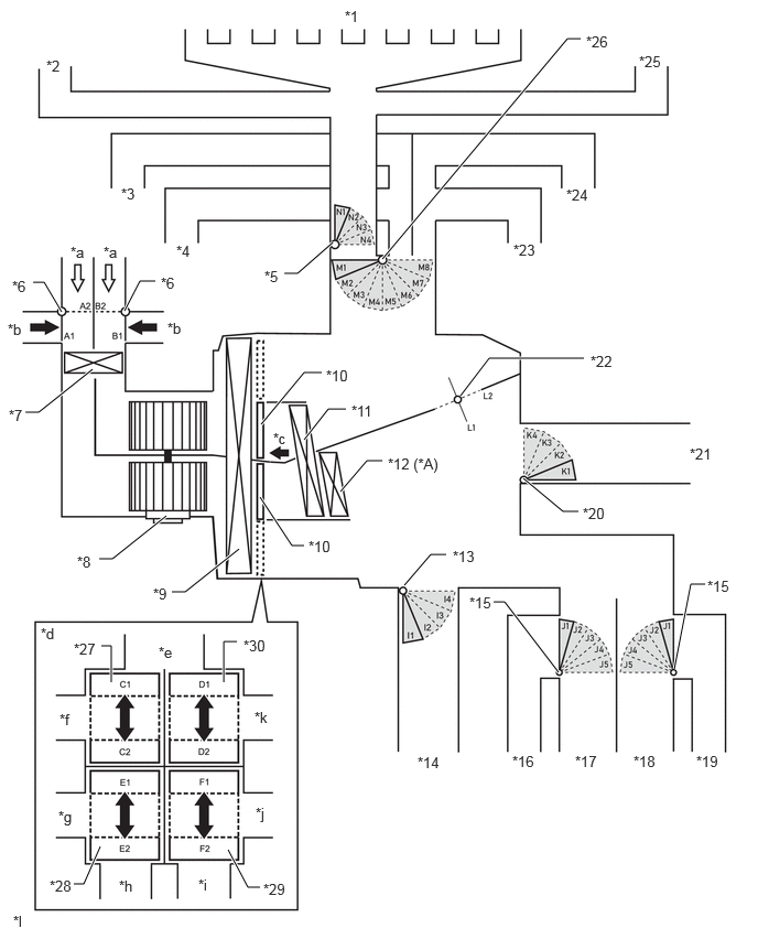
| *A | Models with PTC Heater | - | - |
| *1 | Front Defroster Duct | *2 | Side Defroster Duct LH |
| *3 | Side Register Duct LH | *4 | Center Register Duct LH |
| *5 | DEF Mode Door | *6 | Fresh / Recirculation Mode Door |
| *7 | Air Refiner Element (Clean Air Filter) | *8 | Blower Motor with Fan Sub-assembly |
| *9 | No. 1 Cooler Evaporator Sub-assembly | *10 | Air Mix Servo Motor |
| *11 | Heater Radiator Unit Sub-assembly | *12 | PTC Heater (Quick Heater Assembly) |
| *13 | FOOT Mode Door LH | *14 | Footwell Duct LH |
| *15 | Rear Passenger Mode Door | *16 | Rear Passenger Footwell Duct LH |
| *17 | Rear Passenger Register Duct LH | *18 | Rear Passenger Register Duct RH |
| *19 | Rear Passenger Footwell Duct RH | *20 | FOOT Mode Door RH |
| *21 | Footwell Duct RH | *22 | Inside-and-outside Dual Air Layer Door |
| *23 | Center Register Duct RH | *24 | Side Register Duct RH |
| *25 | Side Defroster Duct RH | *26 | FACE Mode Door Switching Servo Motor |
| *27 | Upper Layer Air Mix Door LH | *28 | Lower Layer Air Mix Door LH |
| *29 | Lower Layer Air Mix Door RH | *30 | Upper Layer Air Mix Door RH |
| *a | Recirculation Air | *b | Fresh Air |
| *c | [A] View | *d | Illustration Image View from [A] |
| *e | Defroster Duct | *f | Left Side Register Duct |
| *g | Left Side Footwell Duct | *h | Left Side Rear Duct |
| *i | Right Side Rear Duct | *j | Right Side Footwell Duct |
| *k | Right Side Register Duct | *l | This illustration is an image. |
| Control Damper | Operation Position | Damper Position | Operation |
|---|---|---|---|
|
*: Models with multi-zone (4-ZONE) climate control |
|||
| Air Inlet Control Damper | FRESH | A2 B2 |
Allows fresh air to enter. |
| Inside-and-outside Dual Air Layer (Auto Control) | A1 B1 - B2 |
The upper layer automatically switches between outside air and inside air according to the control conditions. The lower layer circulates inside air. | |
| RECIRCULATION | A1 B1 |
Causes internal air to recirculate. | |
| Inside-and-outside Dual Air Layer Control Door | Inside-and-outside Dual Air Layer | L1 - L2 | Separates or integrates the upper layer and lower layer in response to the control conditions to control the inside-and-outside dual air layers. |
| Air Mix Control Damper | MAX COLD to MAX HOT Temperature Setting | C1 - C2 D1 - D2 E1- E2 F1 - F2 G1 - G2* H1 - H2* |
Separates or integrates the upper layer and lower layer in response to the control conditions to control the inside-and-outside dual air layers. |
| Air Outlet Control Damper | FACE 1 | I4 J1 K4 M4 N4 |
Blows air out from the following registers.
·
Driver Side Registers
·
Front Passenger Side Registers
·
Rear Passenger Right Side Registers
·
Rear Passenger Left Side Registers |
| FACE 2 | I3 J2 K3 M1 N4 |
·
Blows air out from the following registers when FACE 2 mode is turned on by auto control.
-
Driver Side Registers
-
Front Passenger Side Registers
-
Rear Passenger Right Side Registers
-
Rear Passenger Left Side Registers
·
Blows small amounts of air out from the following registers.
-
Driver Side Footwell Register
-
Front Passenger Side Footwell Register
-
Rear Passenger Right Side Footwell Register
-
Rear Passenger Left Side Footwell Register |
|
| FACE A/M | I4 J1 K4 M2 N4 |
Blows air out from the following registers when FACE A/M mode is turned on by auto control.
·
Driver Side Registers
·
Front Passenger Side Registers
·
Rear Passenger Right Side Registers
·
Rear Passenger Left Side Registers |
|
| BI-LEVEL | I2 J2 K2 M3 N4 |
·
Blows air out from the following registers.
-
Driver Side Registers
-
Driver Side Footwell Register
-
Front Passenger Side Registers
-
Front Passenger Side Footwell Register
-
Rear Passenger Right Side Registers
-
Rear Passenger Right Side Footwell Register
-
Rear Passenger Left Side Registers
-
Rear Passenger Left Side Footwell Register |
|
| FOOT D | I2 J3 K2 M5 N2 |
·
Blows air out from the following registers when FOOT D mode is turned on by auto control.
-
Driver Side Footwell Register
-
Front Passenger Side Footwell Register
-
Rear Passenger Right Side Footwell Register
-
Rear Passenger Left Side Footwell Register
-
Defrosters
·
Blows small amounts of air out from the following registers.
-
Driver Side Registers
-
Front Passenger Sidel Registers
-
Rear Passenger Right Side Register
-
Rear Passenger Left Side Register |
|
| FOOT R | I2 J3 K2 M6 N3 |
·
Blows air out from the following registers.
-
Driver Side Footwell Register
-
Front Passenger Side Footwell Register
-
Rear Passenger Right Side Footwell Register
-
Rear Passenger Left Side Footwell Register
·
Blows small amounts of air out from the following registers.
-
Driver Side Registers
-
Front Passenger Side Registers
-
Rear Passenger Right Side Registers
-
Rear Passenger Left Side Registers
-
Defrosters |
|
| FOOT F | I1 J3 K1 M5 N3 |
·
Blows air out from the following registers when FOOT F mode is turned on by auto control.
-
Driver Side Footwell Register
-
Passenger Side Footwell Register
·
Blows small amounts of air out from the following registers.
-
Driver Side Registers
-
Front Passenger Side Registers
-
Rear Passenger Right Side Registers
-
Rear Passenger Right Side Footwell Register
-
Rear Passenger Left Side Registers
-
Rear Passenger Left Side Footwell Register
-
Defrosters |
|
| FOOT/DEF | I2 J4 K2 M4 N1 |
·
Blows air out from the following registers.
-
Driver Side Footwell Register
-
Passenger Side Footwell Register
-
Rear Passenger Right Side Footwell Register
-
Rear Passenger Left Side Footwell Register
-
Defrosters
·
Blows small amounts of air out from the following registers.
-
Driver Side Registers
-
Front Passenger Side Registers
-
Rear Passenger Right Side Registers
-
Rear Passenger Left Side Registers |
|
| DEF | I4 J5 K4 M8 N1 |
Blows air out from the following registers.
·
Defrosters |
|
Registers and Air Flow Volume Distribution
When it is determined that a rear door is not opened and closed as someone enters the vehicle, the air flow operation is switched automatically to front seat control according to conditions such as the occupants, set temperature, ambient temperature, cabin temperature and sunlight.
- HINT:
-
The S-FLOW control can be switched on/off by operating the S-FLOW switch positioned in the air conditioning operation screen of the multi display.
| S-FLOW Control | Mode | When the cool down transitional period and thermal load are large | When constant (temperature inside vehicle, etc., is stable) and thermal load is small | When the warm up transitional period and thermal load are large |
|---|---|---|---|---|
| ON | S-FLOW (Front Seat Control Modes) | Front Seat Control | All Seat Control Modes | |
| OFF | Normal Control Operating | All Seat Control Modes | ||
Air Outlets and Airflow Volume (for All Seat Control Modes)
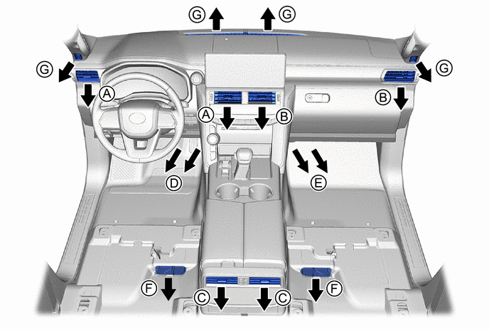
| Mode | Register | Footwell Register | Defroster | |||
|---|---|---|---|---|---|---|
| Front : A, B | Rear : C | Front : D, E | Rear : F | G | ||

|
FACE 1 |

|

|

|
|
|
| FACE 2 |

|
|

|
|
|
|
| FACE A/M |
|
|
|
|
|
|

|
BI-LEVEL |
|
|
|
|
|

|
FOOT D |
|
|
|
|
|
| FOOT R |
|
|
|
|
|
|
| FOOT F |
|
|
|
|
|
|

|
FOOT/DEF |
|
|
|
|
|

|
DEF |
|
|
|
|
|
- HINT:
-
The airflow volume from each air outlet is only for reference.
Air Outlets and Airflow Volume (for Front Seat Control Modes)
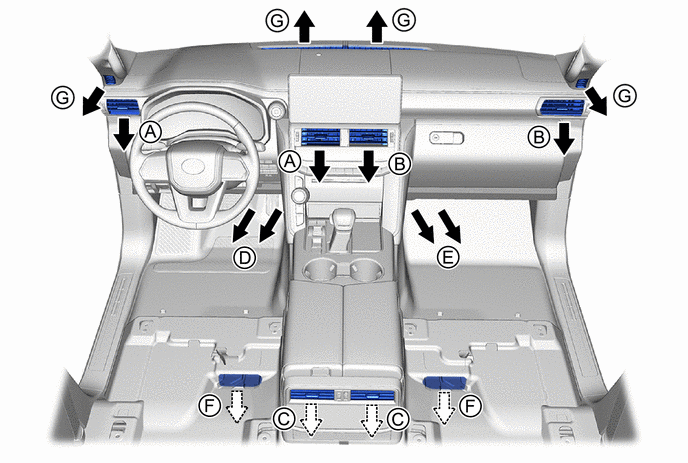
| Mode | Register | Footwell Register | Defroster | |||
|---|---|---|---|---|---|---|
| Front : A, B | Rear : C | Front : D, E | Rear : F | G | ||
|
|
FACE 1 |
|
|
|
|
|
| FACE 2 |
|
|
|
|
|
|
| FACE A/M |
|
|
|
|
|
|
|
|
BI-LEVEL |
|
|
|
|
|
|
|
FOOT D |
|
|
|
|
|
| FOOT R |
|
|
|
|
|
|
| FOOT F |
|
|
|
|
|
|
|
|
FOOT/DEF |
|
|
|
|
|
|
|
DEF |
|
|
|
|
|
- HINT:
-
The airflow volume from each air outlet is only for reference.