SUSPENSION CONTROL ELECTRONIC-KINETIC DYNAMIC SUSPENSION SYSTEM DETAILS STABILIZER CONTROL VALVE
CONSTRUCTION
The stabilizer control valve sub-assembly is composed of an accumulator cut valve, oil supply valve and bleeder plug.
The accumulator cut valve is normally open, and changes to the oil volume caused by temperature changes on the front cylinder side are absorbed by sending excess volume to the accumulator side. When the stabilizer is locked, pressure on the front cylinder side is increased by operations such as turning, and this pressure rise causes the check ball to close, maintaining the pressure.
The oil supply valve is used when filling oil.
The bleeder plug is used for air bleeding when filling oil.
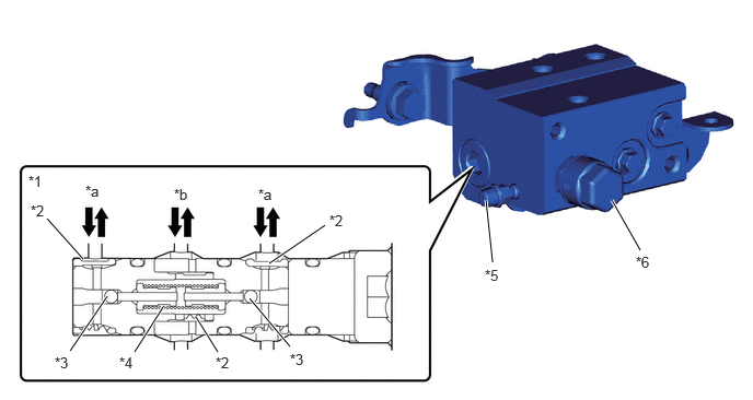
| *1 | Accumulator Cut Valve | *2 | Filter |
| *3 | Check Ball | *4 | Spring |
| *5 | Bleeder Plug | *6 | Oil Supply Valve |
| *a | To Front Stabilizer Control Cylinder | *b | To Accumulator |
The front normal open solenoid valve and front normal closed solenoid valve open and close according to the signals from the stabilizer control ECU to switch the oil passages on the front cylinder side.
The front normal open solenoid valve and front normally closed solenoid valve open and close according to the signals from the stabilizer control ECU to switch the oil passages on the front cylinder side. When the stabilizer is locked, the oil passages are switched to suppress the expansion and contraction of the front cylinder, and when the stabilizer is free, the oil passages are switched in order to expand and contract the front cylinder. Also, in the event of a malfunction such as a power source failure, oil flows to the orifice inside the front normal open solenoid valve to generate damping force. This damping force suppresses the expansion and contraction of the front cylinder, and the stabilizer is set close to the locked condition to ensure driving stability during a malfunction.
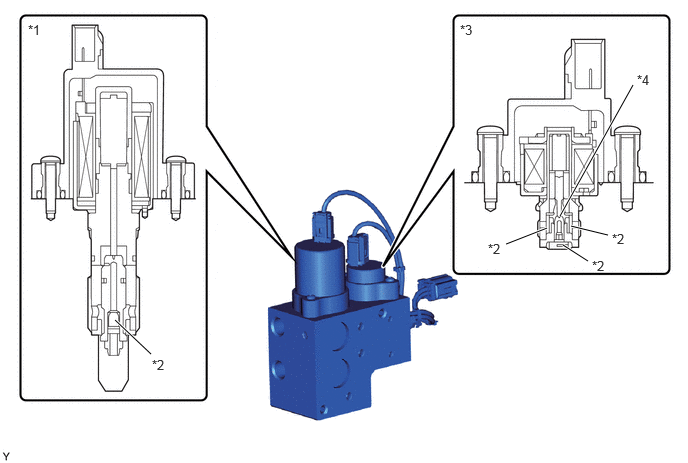
| *1 | Front Normal Closed Solenoid Valve | *2 | Filter |
| *3 | Front Normal Open Solenoid Valve | *4 | Orifice |
The stabilizer control housing with accumulator assembly is composed of a rear lower chamber solenoid valve, rear upper chamber solenoid valve and accumulator.
The rear lower chamber solenoid valve and rear upper chamber solenoid valve open and close according to the signals from the stabilizer control ECU to switch the oil passages on the rear cylinder side. When the stabilizer is locked, the oil passages are switched to suppress the expansion and contraction of the rear cylinder, and when the stabilizer is free, the oil passages are switched in order to expand and contract the rear cylinder.
The accumulator absorb changes to the oil volume caused by temperature changes on the front cylinder side and rear cylinder side. Also, on the rear cylinder side, changes to the oil volume caused by entry of the rod of the rear cylinder are absorbed.
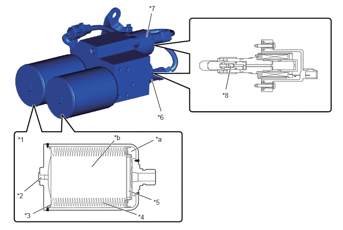
| *1 | Accumulator | *2 | Gas Plug |
| *3 | Backup Oil | *4 | Bellows |
| *5 | Self-sealing | *6 | Rear Upper Chamber Solenoid Valve |
| *7 | Rear Lower Chamber Solenoid Valve | *8 | Filter |
| *a | Oil Chamber | *b | Gas Chamber |