Home › Suspension › SUSPENSION CONTROL › ELECTRONIC-KINETIC DYNAMIC SUSPENSION SYSTEM
NM38G0E _53 Suspension _102385 SUSPENSION CONTROL _0479576 ELECTRONIC-KINETIC DYNAMIC SUSPENSION SYSTEM DE DETAILS F

SUSPENSION CONTROL  ELECTRONIC-KINETIC DYNAMIC SUSPENSION SYSTEM  DETAILS  ELECTRONIC-KINETIC DYNAMIC SUSPENSION CONTROL  


CONSTRUCTION


a.

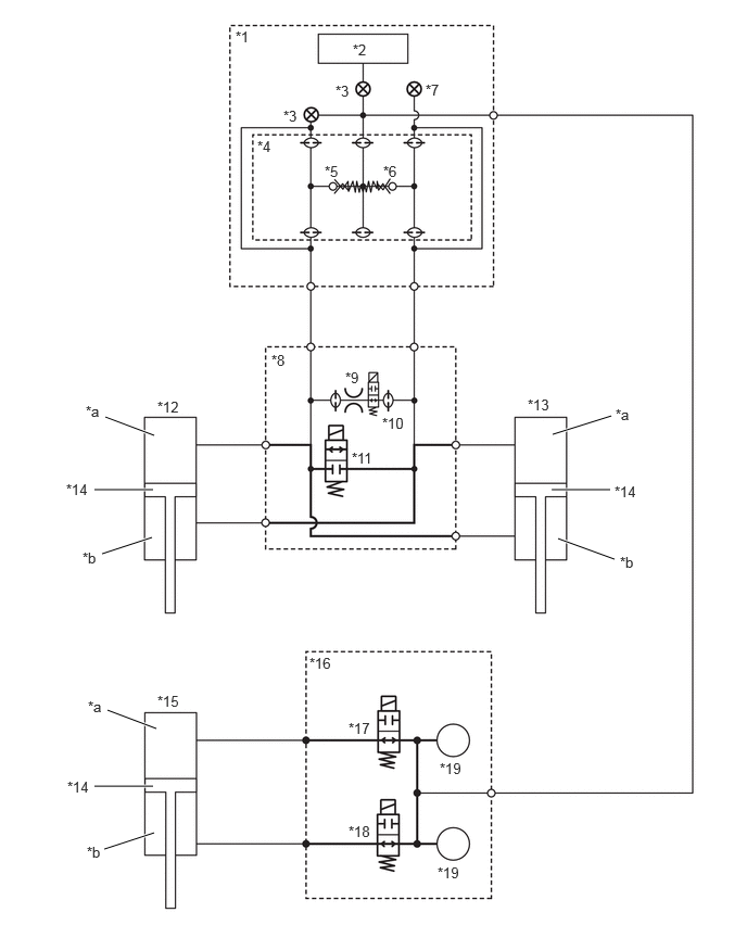
Electronic-Kinetic Dynamic Suspension System (E-KDSS) hydraulic pressure control is composed of components such as an accumulator cut valve, front normal open solenoid valve, front normally closed solenoid valve, rear lower chamber solenoid valve and rear upper chamber solenoid valve. The stabilizer is switched between locked and free by switching the oil passages to the front stabilizer control cylinder and rear stabilizer control cylinder.
Hydraulic Circuit Diagram
X149409C01
1.01,4 1.479,4.177 true 0.906,4.698 1.469,4.698 true 0.979,5.313 1.458,5.156 true 1,8.146 1.479,7.99 true 0.906,7.542 1.469,7.542 true 1.031,6.813 1.5,6.99 true 5.292,4.698 5.854,4.698 true 5.302,4.167 5.865,3.99 true 5.354,5.167 5.896,5.365 true 2.26,0.271 2.573,0.427 0.313,0.156 10 false *1 3.385,0.396 3.698,0.552 0.313,0.156 10 false *2 2.719,1.031 3.031,1.188 0.313,0.156 10 false *3 2.469,1.323 2.781,1.479 0.313,0.156 10 false *4 3.115,1.563 3.427,1.719 0.313,0.156 10 false *5 3.677,1.563 3.99,1.719 0.313,0.156 10 false *6 4.083,0.781 4.396,0.938 0.313,0.156 10 false *7 2.604,3.375 2.917,3.531 0.313,0.156 10 false *8 3.313,3.542 3.625,3.698 0.313,0.156 10 false *9 3.667,3.979 4.135,4.135 0.469,0.156 10 false *10 3.375,4.313 3.844,4.469 0.469,0.156 10 false *11 1.51,3.823 1.979,3.979 0.469,0.156 10 false *12 5.063,3.802 5.531,3.958 0.469,0.156 10 false *13 5.896,4.635 6.365,4.792 0.469,0.156 10 false *14 1.51,6.646 1.979,6.802 0.469,0.156 10 false *15 2.969,6.281 3.438,6.438 0.469,0.156 10 false *16 3.344,6.906 3.813,7.063 0.469,0.156 10 false *17 3.344,7.896 3.813,8.052 0.469,0.156 10 false *18 4.219,7.292 4.688,7.448 0.469,0.156 10 false *19 0.823,3.865 1.135,4.021 0.313,0.156 10 false *a 0.792,5.271 1.104,5.427 0.313,0.156 10 false *b 3.219,0.792 3.531,0.948 0.313,0.156 10 false *3 0.635,4.615 1.104,4.771 0.469,0.156 10 false *14 4.198,8.292 4.667,8.448 0.469,0.156 10 false *19 5.906,3.896 6.219,4.052 0.313,0.156 10 false *a 5.948,5.313 6.26,5.469 0.313,0.156 10 false *b 0.844,6.698 1.156,6.854 0.313,0.156 10 false *a 0.646,7.469 1.115,7.625 0.469,0.156 10 false *14 0.833,8.094 1.146,8.25 0.313,0.156 10 false *b
*1 Stabilizer Control Valve Sub-assembly *2 Oil Supply Valve
*3 Cut Valve *4 Accumulator Cut Valve
*5 Check Ball A *6 Check Ball B
*7 Bleeder Plug *8 Front Stabilizer Housing Sub-assembly
*9 Orifice *10 Front Normal Open Solenoid Valve
*11 Front Normal Closed Solenoid Valve *12 Front Stabilizer Control Cylinder LH
*13 Front Stabilizer Control Cylinder *14 Piston
*15 Rear Stabilizer Control Cylinder *16 Stabilizer Control with Accumulator Housing Assembly
*17 Rear Upper Chamber Solenoid Valve *18 Rear Lower Chamber Solenoid Valve
*19 Accumulator - -
*a Upper Chamber *b Lower Chamber


OPERATION


a.

Normal Operation (Stabilizer Free)

i.

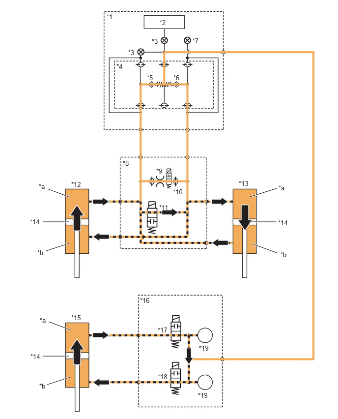
When the stabilizer is free, the front normal open solenoid valve, front normally closed solenoid valve, rear lower chamber solenoid valve and rear upper chamber solenoid valve are all open. At this time, the oil on the front side is balanced between left and right, and the oil on the rear side is balanced between the upper chamber and lower chamber. This oil flow enables the vertical expansion and contraction of the front stabilizer control cylinder and rear stabilizer control cylinder, which sets the stabilizer to free.
Turning Right (Illustration Shows a Representative Example)
X149410C01
1.01,4 1.479,4.177 true 0.906,4.698 1.469,4.698 true 0.979,5.313 1.458,5.156 true 1,8.146 1.479,7.99 true 0.906,7.542 1.469,7.542 true 1.031,6.813 1.5,6.99 true 5.292,4.698 5.854,4.698 true 5.302,4.167 5.865,3.99 true 5.354,5.167 5.896,5.365 true 2.26,0.271 2.573,0.427 0.313,0.156 10 false *1 3.385,0.396 3.698,0.552 0.313,0.156 10 false *2 2.719,1.031 3.031,1.188 0.313,0.156 10 false *3 2.469,1.323 2.781,1.479 0.313,0.156 10 false *4 3.115,1.563 3.427,1.719 0.313,0.156 10 false *5 3.677,1.563 3.99,1.719 0.313,0.156 10 false *6 4.083,0.781 4.396,0.938 0.313,0.156 10 false *7 2.604,3.375 2.917,3.531 0.313,0.156 10 false *8 3.313,3.542 3.625,3.698 0.313,0.156 10 false *9 3.667,3.979 4.135,4.135 0.469,0.156 10 false *10 3.375,4.313 3.844,4.469 0.469,0.156 10 false *11 1.51,3.823 1.979,3.979 0.469,0.156 10 false *12 5.063,3.802 5.531,3.958 0.469,0.156 10 false *13 5.896,4.635 6.365,4.792 0.469,0.156 10 false *14 1.51,6.646 1.979,6.802 0.469,0.156 10 false *15 2.969,6.281 3.438,6.438 0.469,0.156 10 false *16 3.344,6.906 3.813,7.063 0.469,0.156 10 false *17 3.344,7.896 3.813,8.052 0.469,0.156 10 false *18 4.219,7.292 4.688,7.448 0.469,0.156 10 false *19 0.823,3.865 1.135,4.021 0.313,0.156 10 false *a 0.792,5.271 1.104,5.427 0.313,0.156 10 false *b 3.219,0.792 3.531,0.948 0.313,0.156 10 false *3 0.635,4.615 1.104,4.771 0.469,0.156 10 false *14 4.198,8.292 4.667,8.448 0.469,0.156 10 false *19 5.906,3.896 6.219,4.052 0.313,0.156 10 false *a 5.948,5.313 6.26,5.469 0.313,0.156 10 false *b 0.844,6.698 1.156,6.854 0.313,0.156 10 false *a 0.646,7.469 1.115,7.625 0.469,0.156 10 false *14 0.833,8.094 1.146,8.25 0.313,0.156 10 false *b
*1 Stabilizer Control Valve Sub-assembly *2 Oil Supply Valve
*3 Cut Valve *4 Accumulator Cut Valve
*5 Check Ball A *6 Check Ball B
*7 Bleeder Plug *8 Front Stabilizer Housing Sub-assembly
*9 Orifice *10 Front Normal Open Solenoid Valve
*11 Front Normal Closed Solenoid Valve *12 Front Stabilizer Control Cylinder LH
*13 Front Stabilizer Control Cylinder *14 Piston
*15 Rear Stabilizer Control Cylinder *16 Stabilizer Control with Accumulator Housing Assembly
*17 Rear Upper Chamber Solenoid Valve *18 Rear Lower Chamber Solenoid Valve
*19 Accumulator - -
*a Upper Chamber *b Lower Chamber


Valve Operation While Stabilizer Free (Turning Right)
Accumulator Cut Valve Check Ball A Open
Check Ball B Open
Front Normal Open Solenoid Valve OFF (Open)
Front Normal Closed Solenoid Valve ON (Open)
Rear Upper Chamber Solenoid Valve OFF (Open)
Rear Lower Chamber Solenoid Valve OFF (Open)


b.

Normal Operation (Stabilizer Locked)

i.

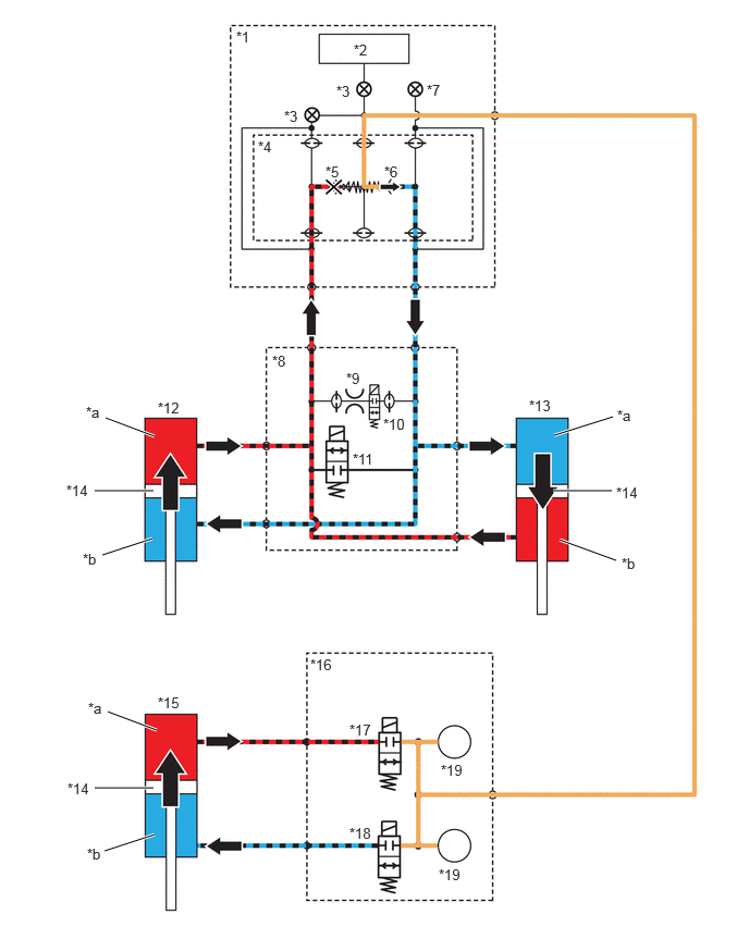
When the stabilizer is locked, the front normal open solenoid valve, front normally closed solenoid valve, rear lower chamber solenoid valve and rear upper chamber solenoid valve are all closed. On the front side, when pressure is applied to one oil passage due to operations such as turning, the ball valve on the side subject to the pressure of the accumulator cut valve is closed to maintain the pressure on the front side. On the rear side, the pressure is maintained by closing the solenoid valve. This maintenance of pressure suppresses the expansion and contraction of the front stabilizer control cylinder and rear stabilizer control cylinder, which sets the stabilizer to locked.
Turning Right (Illustration Shows a Representative Example)
X149411C01
1.01,4 1.479,4.177 true 0.906,4.698 1.469,4.698 true 0.979,5.313 1.458,5.156 true 1,8.146 1.479,7.99 true 0.906,7.542 1.469,7.542 true 1.031,6.813 1.5,6.99 true 5.292,4.698 5.854,4.698 true 5.302,4.167 5.865,3.99 true 5.354,5.167 5.896,5.365 true 2.26,0.271 2.573,0.427 0.313,0.156 10 false *1 3.385,0.396 3.698,0.552 0.313,0.156 10 false *2 2.719,1.031 3.031,1.188 0.313,0.156 10 false *3 2.469,1.323 2.781,1.479 0.313,0.156 10 false *4 3.115,1.563 3.427,1.719 0.313,0.156 10 false *5 3.677,1.563 3.99,1.719 0.313,0.156 10 false *6 4.083,0.781 4.396,0.938 0.313,0.156 10 false *7 2.604,3.375 2.917,3.531 0.313,0.156 10 false *8 3.313,3.542 3.625,3.698 0.313,0.156 10 false *9 3.667,3.979 4.135,4.135 0.469,0.156 10 false *10 3.375,4.313 3.844,4.469 0.469,0.156 10 false *11 1.51,3.823 1.979,3.979 0.469,0.156 10 false *12 5.063,3.802 5.531,3.958 0.469,0.156 10 false *13 5.896,4.635 6.365,4.792 0.469,0.156 10 false *14 1.51,6.646 1.979,6.802 0.469,0.156 10 false *15 2.969,6.281 3.438,6.438 0.469,0.156 10 false *16 3.344,6.906 3.813,7.063 0.469,0.156 10 false *17 3.344,7.896 3.813,8.052 0.469,0.156 10 false *18 4.219,7.292 4.688,7.448 0.469,0.156 10 false *19 0.823,3.865 1.135,4.021 0.313,0.156 10 false *a 0.792,5.271 1.104,5.427 0.313,0.156 10 false *b 3.219,0.792 3.531,0.948 0.313,0.156 10 false *3 0.635,4.615 1.104,4.771 0.469,0.156 10 false *14 4.198,8.292 4.667,8.448 0.469,0.156 10 false *19 5.906,3.896 6.219,4.052 0.313,0.156 10 false *a 5.948,5.313 6.26,5.469 0.313,0.156 10 false *b 0.844,6.698 1.156,6.854 0.313,0.156 10 false *a 0.646,7.469 1.115,7.625 0.469,0.156 10 false *14 0.833,8.094 1.146,8.25 0.313,0.156 10 false *b
*1 Stabilizer Control Valve Sub-assembly *2 Oil Supply Valve
*3 Cut Valve *4 Accumulator Cut Valve
*5 Check Ball A *6 Check Ball B
*7 Bleeder Plug *8 Front Stabilizer Housing Sub-assembly
*9 Orifice *10 Front Normal Open Solenoid Valve
*11 Front Normal Closed Solenoid Valve *12 Front Stabilizer Control Cylinder LH
*13 Front Stabilizer Control Cylinder *14 Piston
*15 Rear Stabilizer Control Cylinder *16 Stabilizer Control with Accumulator Housing Assembly
*17 Rear Upper Chamber Solenoid Valve *18 Rear Lower Chamber Solenoid Valve
*19 Accumulator - -
*a Upper Chamber *b Lower Chamber


Valve Operation While Stabilizer Locked (Turning Right)
Accumulator Cut Valve Check Ball A Closed
Check Ball B Open
Front Normal Open Solenoid Valve ON (Closed)
Front Normal Closed Solenoid Valve OFF (Closed)
Rear Upper Chamber Solenoid Valve ON (Closed)
Rear Lower Chamber Solenoid Valve ON (Closed)


c.

During Malfunction (Power Source Failure, etc.)

i.

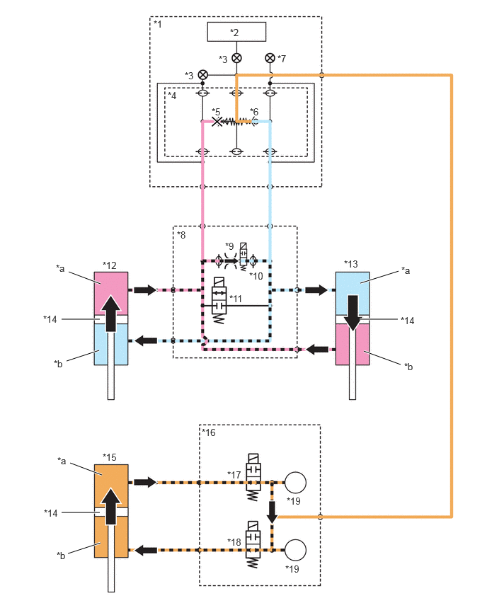
During a malfunction, the front normal open solenoid valve, rear lower chamber solenoid valve and rear upper chamber solenoid valve are open, and the front normally closed solenoid valve is closed. On the front side, when pressure is applied to one oil passage due to operations such as turning, oil flows to the orifice inside the front normal open solenoid valve to generate damping force. On the rear side, the rear stabilizer control cylinder can expand and contract because the solenoid valve is open, which sets the stabilizer to free. Therefore, the stabilizer on the front side is locked and the stabilizer on the rear side is free, which results in a tendency for the vehicle to understeer, ensuring driving stability when a malfunction occurs.
Turning Right (Illustration Shows a Representative Example)
X149412C01
1.01,4 1.479,4.177 true 0.906,4.698 1.469,4.698 true 0.979,5.313 1.458,5.156 true 1,8.146 1.479,7.99 true 0.906,7.542 1.469,7.542 true 1.031,6.813 1.5,6.99 true 5.292,4.698 5.854,4.698 true 5.302,4.167 5.865,3.99 true 5.354,5.167 5.896,5.365 true 2.26,0.271 2.573,0.427 0.313,0.156 10 false *1 3.385,0.396 3.698,0.552 0.313,0.156 10 false *2 2.719,1.031 3.031,1.188 0.313,0.156 10 false *3 2.469,1.323 2.781,1.479 0.313,0.156 10 false *4 3.115,1.563 3.427,1.719 0.313,0.156 10 false *5 3.677,1.563 3.99,1.719 0.313,0.156 10 false *6 4.083,0.781 4.396,0.938 0.313,0.156 10 false *7 2.604,3.375 2.917,3.531 0.313,0.156 10 false *8 3.313,3.542 3.625,3.698 0.313,0.156 10 false *9 3.667,3.979 4.135,4.135 0.469,0.156 10 false *10 3.375,4.313 3.844,4.469 0.469,0.156 10 false *11 1.51,3.823 1.979,3.979 0.469,0.156 10 false *12 5.063,3.802 5.531,3.958 0.469,0.156 10 false *13 5.896,4.635 6.365,4.792 0.469,0.156 10 false *14 1.51,6.646 1.979,6.802 0.469,0.156 10 false *15 2.969,6.281 3.438,6.438 0.469,0.156 10 false *16 3.344,6.906 3.813,7.063 0.469,0.156 10 false *17 3.344,7.896 3.813,8.052 0.469,0.156 10 false *18 4.219,7.292 4.688,7.448 0.469,0.156 10 false *19 0.823,3.865 1.135,4.021 0.313,0.156 10 false *a 0.792,5.271 1.104,5.427 0.313,0.156 10 false *b 3.219,0.792 3.531,0.948 0.313,0.156 10 false *3 0.635,4.615 1.104,4.771 0.469,0.156 10 false *14 4.198,8.292 4.667,8.448 0.469,0.156 10 false *19 5.906,3.896 6.219,4.052 0.313,0.156 10 false *a 5.948,5.313 6.26,5.469 0.313,0.156 10 false *b 0.844,6.698 1.156,6.854 0.313,0.156 10 false *a 0.646,7.469 1.115,7.625 0.469,0.156 10 false *14 0.833,8.094 1.146,8.25 0.313,0.156 10 false *b
*1 Stabilizer Control Valve Sub-assembly *2 Oil Supply Valve
*3 Cut Valve *4 Accumulator Cut Valve
*5 Check Ball A *6 Check Ball B
*7 Bleeder Plug *8 Front Stabilizer Housing Sub-assembly
*9 Orifice *10 Front Normal Open Solenoid Valve
*11 Front Normal Closed Solenoid Valve *12 Front Stabilizer Control Cylinder LH
*13 Front Stabilizer Control Cylinder *14 Piston
*15 Rear Stabilizer Control Cylinder *16 Stabilizer Control with Accumulator Housing Assembly
*17 Rear Upper Chamber Solenoid Valve *18 Rear Lower Chamber Solenoid Valve
*19 Accumulator - -
*a Upper Chamber *b Lower Chamber


Valve Operation During Malfunction (Power Source Failure, etc.) (Turning Right)
Accumulator Cut Valve Check Ball A Closed
Check Ball B Open
Front Normal Open Solenoid Valve OFF (Open)
Front Normal Closed Solenoid Valve OFF (Closed)
Rear Upper Chamber Solenoid Valve OFF (Open)
Rear Lower Chamber Solenoid Valve OFF (Open)