BRAKE CONTROL / DYNAMIC CONTROL SYSTEMS BRAKE CONTROL SYSTEM CONTROL ACTIVATE TRACTION CONTROL (A-TRC)
SYSTEM CONTROL
A-TRC provides high driving performance when driving on uneven or muddy road surfaces instead of a mechanical differential lock. This system detects the driving condition with various sensors and uses the No. 2 skid control ECU to control the brake fluid pressure individually for each of the 4 wheels. This suppresses wheel spin and distributes the motive force to provide a powerful Limited Slip Differential (LSD) effect.
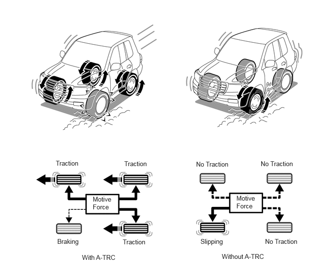
A-TRC Effects
Off-road driving performance equivalent to center differential lock and rear differential lock equipment can be obtained.
Compared to when the differential lock is applied, the differential functions more as originally designed, without the tight corner braking phenomenon, and with superior line-tracing performance and small-radius turning performance.
Vehicle body acceleration caused by the release of the engine brake is suppressed, such as when driving over bumps on a steep downhill slope.
A-TRC Control Description
The vehicle body acceleration condition is detected by the yaw rate sensor, and the tire lock condition and rotation speed of each wheel are detected by the speed sensor. Also, the control target speed for A-TRC is calculated according to the transfer position.
The No. 2 skid control ECU compares the control target speed and the speed of each wheel, determines whether acceleration slipping is occurring, and performs brake fluid pressure control of each wheel.
The ECM receives the A-TRC control signals and performs throttle control to manage the engine output. (Only when the transfer is in H4F mode)
| Road Surface Condition | Transfer Position | Control Description | Description | |
|---|---|---|---|---|
| Normal driving | H4 | Control target speed | Vehicle body speed + slip rate (H position setting) | Control that anticipates ease of driving on low friction surfaces, dirt roads and normal roads. |
| Brake control | Gentle fluid pressure control | |||
| Engine control | Engine output control | |||
| Off-road rocky surfaces, etc. | L4 | Control target speed | Vehicle body speed + slip rate (L position setting) | Control that anticipates rough off-road driving. |
| Brake control | Sudden fluid pressure control | |||
| Engine control | No output control | |||