BRAKE CONTROL / DYNAMIC CONTROL SYSTEMS BRAKE CONTROL SYSTEM DETAILS BRAKE CONTROL
CONSTRUCTION
The brake control system consists of the linear solenoid valve (SLA, SLR, SM1, SM2), gap hold valve (SGH), stroke simulator cut valve (SSA), pressure holding solenoid valve (SFRH, SRLH, SRRH, SFLH), pressure reduction solenoid valve (SFRR, SRLR, SRRR, SFLR), etc., and controls the brake fluid pressure in each wheel cylinder.
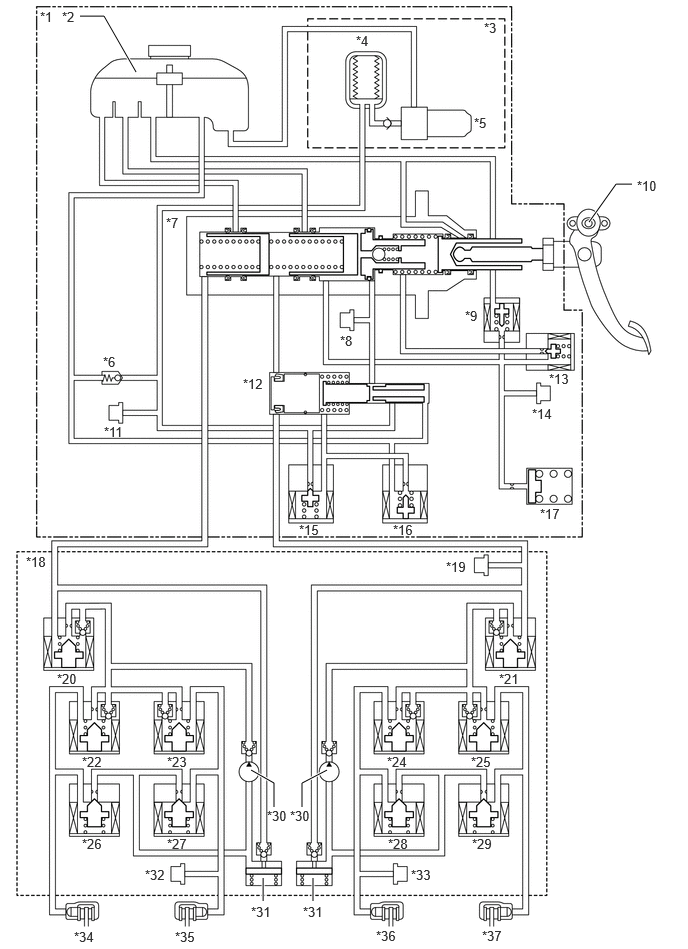
| *1 | Brake Booster with Master Cylinder Assembly | *2 | Brake Master Cylinder Reservoir Assembly |
| *3 | Brake Booster with Accumulator Pump Assembly | *4 | Accumulator |
| *5 | Pump Motor | *6 | Relief Valve |
| *7 | Master Cylinder | *8 | Servo Pressure Sensor (Psrv) |
| *9 | Stroke Simulator Cut Valve (SSA) | *10 | Brake Pedal Stroke Sensor Assembly |
| *11 | Accumulator Pressure Sensor (Pacc) | *12 | Regulator |
| *13 | Gap Hold Valve (SGH) | *14 | Stroke Simulator Pressure Sensor (Prct) |
| *15 | Linear Solenoid Valve (SLA) | *16 | Linear Solenoid Valve (SLR) |
| *17 | Stroke Simulator | *18 | Brake Actuator Assembly |
| *19 | Master Cylinder Pressure Sensor (Pmc) | *20 | Linear Solenoid Valve (SM2) |
| *21 | Linear Solenoid Valve (SM1) | *22 | Pressure Holding Solenoid Valve (SRRH) |
| *23 | Pressure Holding Solenoid Valve (SRLH) | *24 | Pressure Holding Solenoid Valve (SFRH) |
| *25 | Pressure Holding Solenoid Valve (SFLH) | *26 | Pressure Reduction Solenoid Valve (SRRR) |
| *27 | Pressure Reduction Solenoid Valve (SRLR) | *28 | Pressure Reduction Solenoid Valve (SFRR) |
| *29 | Pressure Reduction Solenoid Valve (SFLR) | *30 | Pump |
| *31 | Reservoir | *32 | Wheel Cylinder Pressure Sensor (Pwc2) |
| *33 | Wheel Cylinder Pressure Sensor (Pwc1) | *34 | Rear Brake RH |
| *35 | Rear Brake LH | *36 | Front Brake RH |
| *37 | Front Brake LH | - | - |
For each condition, the open/closed state of each valve is as follows.
Brake Booster with Master Cylinder Assembly
| Without Malfunction | Malfunction | |||||
|---|---|---|---|---|---|---|
| Pressure Control: Activate | Pressure Control: Not Activate | |||||
| Master Cylinder Pressure Increasing Mode | Master Cylinder Pressure Holding Mode | Master Cylinder Pressure Reduction Mode | ||||
| Signals | SLA | ON (Liner Control) | OFF (Closed) | OFF (Closed) | OFF (Closed) | OFF (Closed) |
| SLR | ON (Closed) | ON (Closed) | ON (Liner Control) | OFF (Open) | OFF (Open) | |
| SGH | ON (Open) | ON (Open) | ON (Open) | ON (Open) | OFF (Closed) | |
| SSA | ON (Closed) | ON (Closed) | ON (Closed) | ON (Closed) | OFF (Open) | |
- HINT:
-
·
The solenoid valve controls the brake fluid pressure by continually opening and closing the valve in accordance with the operating conditions.
Brake Actuator Assembly
| Without Malfunction | Malfunction | |||
|---|---|---|---|---|
| Pressure Control: Activate | Pressure Control: Not Activate | |||
| Signals | SM1 | ON (Liner Control) | OFF (Open) | OFF (Open) |
| SM2 | ON (Liner Control) | OFF (Open) | OFF (Open) | |
- HINT:
-
·
The solenoid valve controls the brake fluid pressure by continually opening and closing the valve in accordance with the operating conditions.
| Without Malfunction | Malfunction | |||||
|---|---|---|---|---|---|---|
| Pressure Control: Activate | Pressure Control: Not Activate | |||||
| Wheel Cylinder Pressure Increasing Mode | Wheel Cylinder Pressure Holding Mode | Wheel Cylinder Pressure Reduction Mode | ||||
| Signals | SFRH | OFF (Open) | ON (Closed) | ON (Closed) | OFF (Open) | OFF (Open) |
| SRLH | OFF (Open) | ON (Closed) | ON (Closed) | OFF (Open) | OFF (Open) | |
| SRRH | OFF (Open) | ON (Closed) | ON (Closed) | OFF (Open) | OFF (Open) | |
| SFLH | OFF (Open) | ON (Closed) | ON (Closed) | OFF (Open) | OFF (Open) | |
| SFRR | OFF (Closed) | OFF (Closed) | ON (Open) | OFF (Closed) | OFF (Closed) | |
| SRLR | OFF (Closed) | OFF (Closed) | ON (Open) | OFF (Closed) | OFF (Closed) | |
| SRRR | OFF (Closed) | OFF (Closed) | ON (Open) | OFF (Closed) | OFF (Closed) | |
| SFLR | OFF (Closed) | OFF (Closed) | ON (Open) | OFF (Closed) | OFF (Closed) | |
- HINT:
-
·
The solenoid valve controls the brake fluid pressure by continually opening and closing the valve in accordance with the operating conditions.
OPERATION
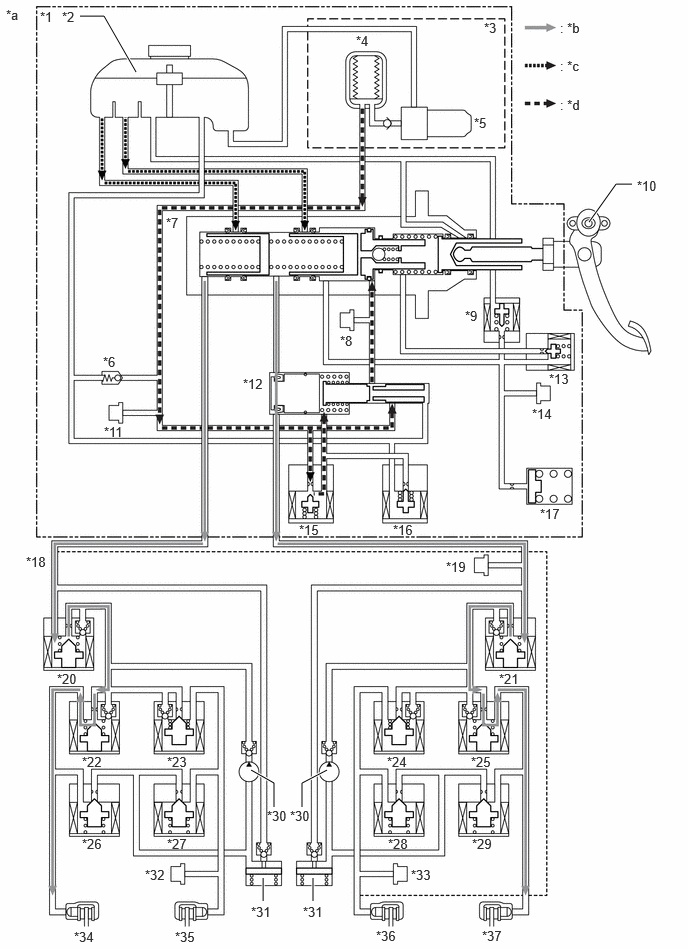
During Normal Operation
During normal braking, the stroke simulator cut valve (SSA) is closed and the gap hold valve (SGH) is open. At this time, pressure from the input piston is applied to the stroke simulator to create brake pedal feel. The pressure generated by the brake booster with master cylinder assembly together with the pressure generated by the brake actuator assembly is optimally adjusted to create a braking force based on the brake pedal depression amount.
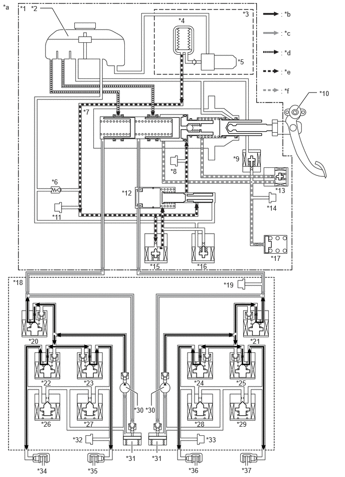
| *1 | Brake Booster with Master Cylinder Assembly | *2 | Brake Master Cylinder Reservoir Assembly |
| *3 | Brake Booster with Accumulator Pump Assembly | *4 | Accumulator |
| *5 | Pump Motor | *6 | Relief Valve |
| *7 | Master Cylinder | *8 | Servo Pressure Sensor (Psrv) |
| *9 | Stroke Simulator Cut Valve (SSA) | *10 | Brake Pedal Stroke Sensor Assembly |
| *11 | Accumulator Pressure Sensor (Pacc) | *12 | Regulator |
| *13 | Gap Hold Valve (SGH) | *14 | Stroke Simulator Pressure Sensor (Prct) |
| *15 | Linear Solenoid Valve (SLA) | *16 | Linear Solenoid Valve (SLR) |
| *17 | Stroke Simulator | *18 | Brake Actuator Assembly |
| *19 | Master Cylinder Pressure Sensor (Pmc) | *20 | Linear Solenoid Valve (SM2) |
| *21 | Linear Solenoid Valve (SM1) | *22 | Pressure Holding Solenoid Valve (SRRH) |
| *23 | Pressure Holding Solenoid Valve (SRLH) | *24 | Pressure Holding Solenoid Valve (SFRH) |
| *25 | Pressure Holding Solenoid Valve (SFLH) | *26 | Pressure Reduction Solenoid Valve (SRRR) |
| *27 | Pressure Reduction Solenoid Valve (SRLR) | *28 | Pressure Reduction Solenoid Valve (SFRR) |
| *29 | Pressure Reduction Solenoid Valve (SFLR) | *30 | Pump |
| *31 | Reservoir | *32 | Wheel Cylinder Pressure Sensor (Pwc2) |
| *33 | Wheel Cylinder Pressure Sensor (Pwc1) | *34 | Rear Brake RH |
| *35 | Rear Brake LH | *36 | Front Brake RH |
| *37 | Front Brake LH | - | - |
| *a | This illustration is an example. | *b | Flow of brake fluid pressurized by the brake actuator assembly |
| *c | Flow of brake fluid pressurized by the brake booster with master cylinder assembly | *d | Flow of brake fluid from the brake master cylinder reservoir assembly |
| *e | Flow of brake fluid for the servo chamber | *f | Flow of brake fluid by pressure generated by brake pedal operation |
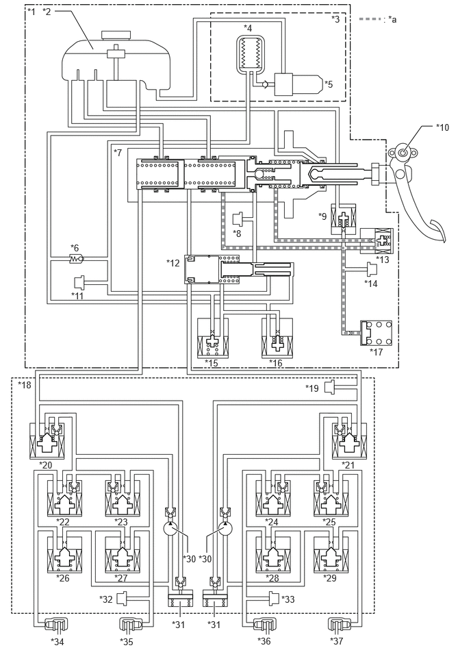
| *1 | Brake Booster with Master Cylinder Assembly | *2 | Brake Master Cylinder Reservoir Assembly |
| *3 | Brake Booster with Accumulator Pump Assembly | *4 | Accumulator |
| *5 | Pump Motor | *6 | Relief Valve |
| *7 | Master Cylinder | *8 | Servo Pressure Sensor (Psrv) |
| *9 | Stroke Simulator Cut Valve (SSA) | *10 | Brake Pedal Stroke Sensor Assembly |
| *11 | Accumulator Pressure Sensor (Pacc) | *12 | Regulator |
| *13 | Gap Hold Valve (SGH) | *14 | Stroke Simulator Pressure Sensor (Prct) |
| *15 | Linear Solenoid Valve (SLA) | *16 | Linear Solenoid Valve (SLR) |
| *17 | Stroke Simulator | *18 | Brake Actuator Assembly |
| *19 | Master Cylinder Pressure Sensor (Pmc) | *20 | Linear Solenoid Valve (SM2) |
| *21 | Linear Solenoid Valve (SM1) | *22 | Pressure Holding Solenoid Valve (SRRH) |
| *23 | Pressure Holding Solenoid Valve (SRLH) | *24 | Pressure Holding Solenoid Valve (SFRH) |
| *25 | Pressure Holding Solenoid Valve (SFLH) | *26 | Pressure Reduction Solenoid Valve (SRRR) |
| *27 | Pressure Reduction Solenoid Valve (SRLR) | *28 | Pressure Reduction Solenoid Valve (SFRR) |
| *29 | Pressure Reduction Solenoid Valve (SFLR) | *30 | Pump |
| *31 | Reservoir | *32 | Wheel Cylinder Pressure Sensor (Pwc2) |
| *33 | Wheel Cylinder Pressure Sensor (Pwc1) | *34 | Rear Brake RH |
| *35 | Rear Brake LH | *36 | Front Brake RH |
| *37 | Front Brake LH | - | - |
| *a | Pressure generated by brake pedal operation (pressure maintained) | - | - |
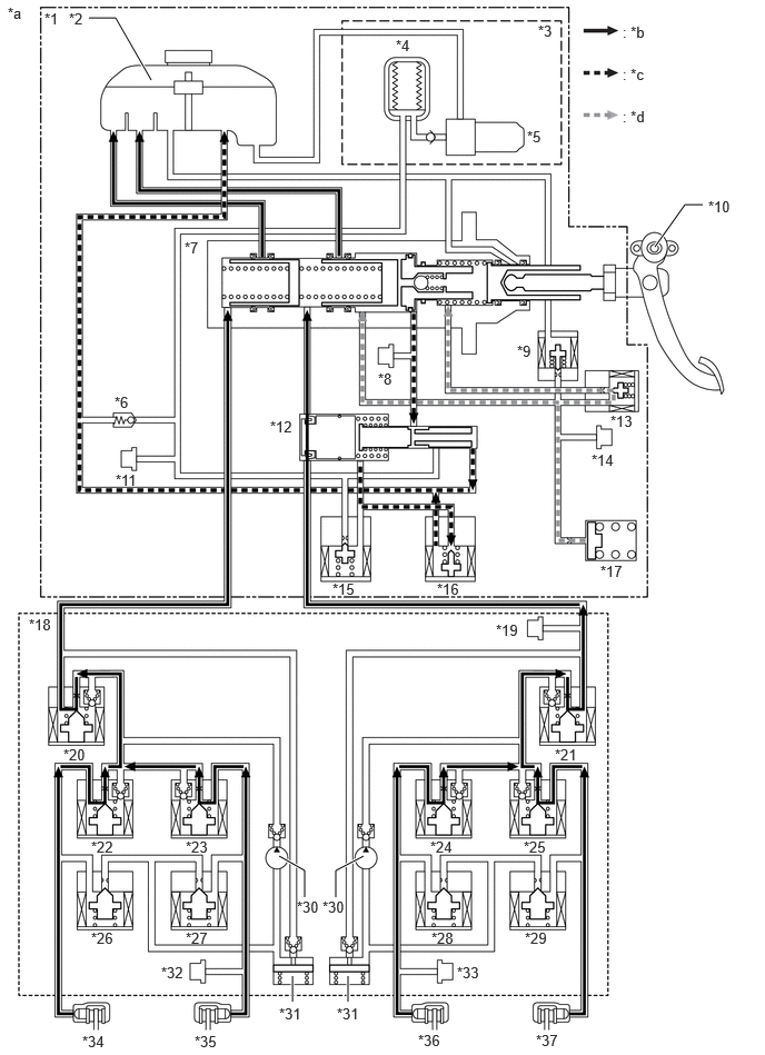
| *1 | Brake Booster with Master Cylinder Assembly | *2 | Brake Master Cylinder Reservoir Assembly |
| *3 | Brake Booster with Accumulator Pump Assembly | *4 | Accumulator |
| *5 | Pump Motor | *6 | Relief Valve |
| *7 | Master Cylinder | *8 | Servo Pressure Sensor (Psrv) |
| *9 | Stroke Simulator Cut Valve (SSA) | *10 | Brake Pedal Stroke Sensor Assembly |
| *11 | Accumulator Pressure Sensor (Pacc) | *12 | Regulator |
| *13 | Gap Hold Valve (SGH) | *14 | Stroke Simulator Pressure Sensor (Prct) |
| *15 | Linear Solenoid Valve (SLA) | *16 | Linear Solenoid Valve (SLR) |
| *17 | Stroke Simulator | *18 | Brake Actuator Assembly |
| *19 | Master Cylinder Pressure Sensor (Pmc) | *20 | Linear Solenoid Valve (SM2) |
| *21 | Linear Solenoid Valve (SM1) | *22 | Pressure Holding Solenoid Valve (SRRH) |
| *23 | Pressure Holding Solenoid Valve (SRLH) | *24 | Pressure Holding Solenoid Valve (SFRH) |
| *25 | Pressure Holding Solenoid Valve (SFLH) | *26 | Pressure Reduction Solenoid Valve (SRRR) |
| *27 | Pressure Reduction Solenoid Valve (SRLR) | *28 | Pressure Reduction Solenoid Valve (SFRR) |
| *29 | Pressure Reduction Solenoid Valve (SFLR) | *30 | Pump |
| *31 | Reservoir | *32 | Wheel Cylinder Pressure Sensor (Pwc2) |
| *33 | Wheel Cylinder Pressure Sensor (Pwc1) | *34 | Rear Brake RH |
| *35 | Rear Brake LH | *36 | Front Brake RH |
| *37 | Front Brake LH | - | - |
| *a | This illustration is an example. | *b | Flow of brake fluid returned from the wheel cylinder |
| *c | Flow of brake fluid returned from the servo chamber | *d | Flow of brake fluid returned from the stroke simulator |
| Master Cylinder Pressure Control | Activate |
| Wheel Cylinder Pressure Control (Linear Solenoid Valve (SM1, SM2)) | Activate |
| Wheel Cylinder Pressure Control (Pressure Holding Solenoid Valve and Pressure Reduction Solenoid Valve) | Not Activate |
ABS and EBD
The ABS and EBD controls the pump, pressure holding solenoid valve and pressure reduction valve to control the brake fluid pressure of each wheel cylinder.
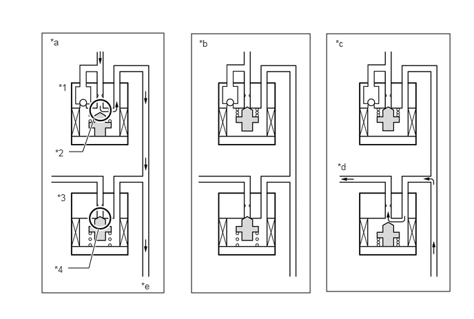
| *1 | Pressure Holding Solenoid Valve | *2 | Port 1 |
| *3 | Pressure Reduction Solenoid Valve | *4 | Port 2 |
| *a | Pressure Increase Mode | *b | Pressure Hold Mode |
| *c | Pressure Decrease Mode | *d | To Reservoir |
| *e | To Wheel Cylinder | - | - |
| Master Cylinder Pressure Control | Activate |
| Wheel Cylinder Pressure Control (Linear Solenoid Valve (SM1, SM2)) | Not Activate |
| Wheel Cylinder Pressure Control (Pressure Holding Solenoid Valve and Pressure Reduction Solenoid Valve) | Activate |
| Master Cylinder Pressure Control | Activate |
| Wheel Cylinder Pressure Control (Linear Solenoid Valve (SM1, SM2)) | Activate |
| Wheel Cylinder Pressure Control (Pressure Holding Solenoid Valve and Pressure Reduction Solenoid Valve) | Activate |
Brake Assist
When brake assist is operating, the brake fluid pressure generated by the brake booster with master cylinder assembly is supplied to the brake actuator assembly. Based on the supplied pressure, by adjusting the brake fluid pressure using the pump motor in the brake actuator assembly, a brake fluid pressure higher than that generated by the driver depressing the brake pedal is directed to each wheel cylinder.
| *1 | Brake Booster with Master Cylinder Assembly | *2 | Brake Master Cylinder Reservoir Assembly |
| *3 | Brake Booster with Accumulator Pump Assembly | *4 | Accumulator |
| *5 | Pump Motor | *6 | Relief Valve |
| *7 | Master Cylinder | *8 | Servo Pressure Sensor (Psrv) |
| *9 | Stroke Simulator Cut Valve (SSA) | *10 | Brake Pedal Stroke Sensor Assembly |
| *11 | Accumulator Pressure Sensor (Pacc) | *12 | Regulator |
| *13 | Gap Hold Valve (SGH) | *14 | Stroke Simulator Pressure Sensor (Prct) |
| *15 | Linear Solenoid Valve (SLA) | *16 | Linear Solenoid Valve (SLR) |
| *17 | Stroke Simulator | *18 | Brake Actuator Assembly |
| *19 | Master Cylinder Pressure Sensor (Pmc) | *20 | Linear Solenoid Valve (SM2) |
| *21 | Linear Solenoid Valve (SM1) | *22 | Pressure Holding Solenoid Valve (SRRH) |
| *23 | Pressure Holding Solenoid Valve (SRLH) | *24 | Pressure Holding Solenoid Valve (SFRH) |
| *25 | Pressure Holding Solenoid Valve (SFLH) | *26 | Pressure Reduction Solenoid Valve (SRRR) |
| *27 | Pressure Reduction Solenoid Valve (SRLR) | *28 | Pressure Reduction Solenoid Valve (SFRR) |
| *29 | Pressure Reduction Solenoid Valve (SFLR) | *30 | Pump |
| *31 | Reservoir | *32 | Wheel Cylinder Pressure Sensor (Pwc2) |
| *33 | Wheel Cylinder Pressure Sensor (Pwc1) | *34 | Rear Brake RH |
| *35 | Rear Brake LH | *36 | Front Brake RH |
| *37 | Front Brake LH | - | - |
| *a | This illustration is an example. | *b | Flow of brake fluid pressurized by the brake actuator assembly |
| *c | Flow of brake fluid pressurized by the brake booster with master cylinder assembly | *d | Flow of brake fluid from the brake master cylinder reservoir assembly |
| *e | Flow of brake fluid for the servo chamber | *f | Flow of brake fluid by pressure generated by brake pedal operation |
| Master Cylinder Pressure Control | Activate |
| Wheel Cylinder Pressure Control (Linear Solenoid Valve (SM1, SM2)) | Activate |
| Wheel Cylinder Pressure Control (Pressure Holding Solenoid Valve and Pressure Reduction Solenoid Valve) | Not Activate |
A-TRC
During A-TRC operation (ROCK mode), the fluid pressure created by the master cylinder in the brake booster assembly (with master cylinder) is sent to the wheel cylinder of the driving wheel that slipped to operate the brake and suppress the wheel slip due to motive force.
The following illustration shows the operation during pressure increase mode.
| *1 | Brake Booster with Master Cylinder Assembly | *2 | Brake Master Cylinder Reservoir Assembly |
| *3 | Brake Booster with Accumulator Pump Assembly | *4 | Accumulator |
| *5 | Pump Motor | *6 | Relief Valve |
| *7 | Master Cylinder | *8 | Servo Pressure Sensor (Psrv) |
| *9 | Stroke Simulator Cut Valve (SSA) | *10 | Brake Pedal Stroke Sensor Assembly |
| *11 | Accumulator Pressure Sensor (Pacc) | *12 | Regulator |
| *13 | Gap Hold Valve (SGH) | *14 | Stroke Simulator Pressure Sensor (Prct) |
| *15 | Linear Solenoid Valve (SLA) | *16 | Linear Solenoid Valve (SLR) |
| *17 | Stroke Simulator | *18 | Brake Actuator Assembly |
| *19 | Master Cylinder Pressure Sensor (Pmc) | *20 | Linear Solenoid Valve (SM2) |
| *21 | Linear Solenoid Valve (SM1) | *22 | Pressure Holding Solenoid Valve (SRRH) |
| *23 | Pressure Holding Solenoid Valve (SRLH) | *24 | Pressure Holding Solenoid Valve (SFRH) |
| *25 | Pressure Holding Solenoid Valve (SFLH) | *26 | Pressure Reduction Solenoid Valve (SRRR) |
| *27 | Pressure Reduction Solenoid Valve (SRLR) | *28 | Pressure Reduction Solenoid Valve (SFRR) |
| *29 | Pressure Reduction Solenoid Valve (SFLR) | *30 | Pump |
| *31 | Reservoir | *32 | Wheel Cylinder Pressure Sensor (Pwc2) |
| *33 | Wheel Cylinder Pressure Sensor (Pwc1) | *34 | Rear Brake RH |
| *35 | Rear Brake LH | *36 | Front Brake RH |
| *37 | Front Brake LH | - | - |
| *a | This illustration is an example. | *b | Flow of brake fluid pressurized by the brake booster with master cylinder assembly |
| *c | Flow of brake fluid from the brake master cylinder reservoir assembly | *d | Flow of brake fluid for the servo chamber |
| Master Cylinder Pressure Control | Activate |
| Wheel Cylinder Pressure Control (Linear Solenoid Valve (SM1, SM2)) | Activate |
| Wheel Cylinder Pressure Control (Pressure Holding Solenoid Valve and Pressure Reduction Solenoid Valve) | Activate |
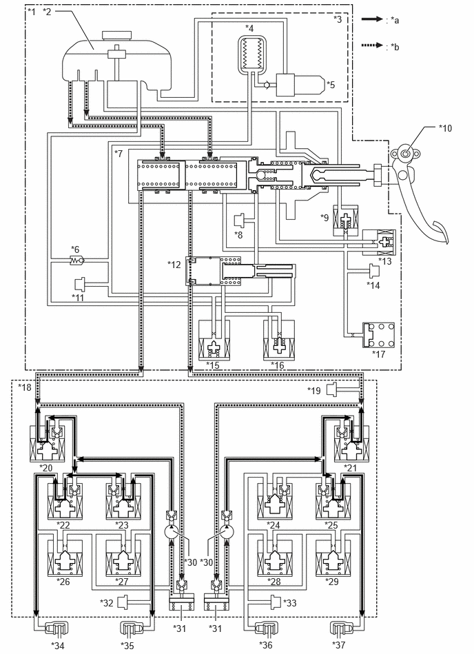
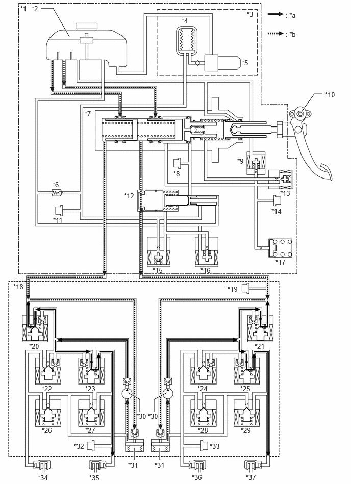
VSC
When VSC is operating, pressurized brake fluid is supplied by the pumps of the brake actuator to the wheel cylinder of each wheel, and lateral slippage of the front and rear wheels is suppressed by controlling the brake fluid pressure.
Both of the following illustrations show the operation during pressure increase mode when the driver is not depressing the brake pedal while cornering to the right.
| *1 | Brake Booster with Master Cylinder Assembly | *2 | Brake Master Cylinder Reservoir Assembly |
| *3 | Brake Booster with Accumulator Pump Assembly | *4 | Accumulator |
| *5 | Pump Motor | *6 | Relief Valve |
| *7 | Master Cylinder | *8 | Servo Pressure Sensor (Psrv) |
| *9 | Stroke Simulator Cut Valve (SSA) | *10 | Brake Pedal Stroke Sensor Assembly |
| *11 | Accumulator Pressure Sensor (Pacc) | *12 | Regulator |
| *13 | Gap Hold Valve (SGH) | *14 | Stroke Simulator Pressure Sensor (Prct) |
| *15 | Linear Solenoid Valve (SLA) | *16 | Linear Solenoid Valve (SLR) |
| *17 | Stroke Simulator | *18 | Brake Actuator Assembly |
| *19 | Master Cylinder Pressure Sensor (Pmc) | *20 | Linear Solenoid Valve (SM2) |
| *21 | Linear Solenoid Valve (SM1) | *22 | Pressure Holding Solenoid Valve (SRRH) |
| *23 | Pressure Holding Solenoid Valve (SRLH) | *24 | Pressure Holding Solenoid Valve (SFRH) |
| *25 | Pressure Holding Solenoid Valve (SFLH) | *26 | Pressure Reduction Solenoid Valve (SRRR) |
| *27 | Pressure Reduction Solenoid Valve (SRLR) | *28 | Pressure Reduction Solenoid Valve (SFRR) |
| *29 | Pressure Reduction Solenoid Valve (SFLR) | *30 | Pump |
| *31 | Reservoir | *32 | Wheel Cylinder Pressure Sensor (Pwc2) |
| *33 | Wheel Cylinder Pressure Sensor (Pwc1) | *34 | Rear Brake RH |
| *35 | Rear Brake LH | *36 | Front Brake RH |
| *37 | Front Brake LH | - | - |
| *a | Flow of brake fluid pressurized by the brake actuator assembly | *b | Flow of brake fluid from the brake master cylinder reservoir assembly |
| Master Cylinder Pressure Control | Not Activate |
| Wheel Cylinder Pressure Control (Linear Solenoid Valve (SM1, SM2)) | Activate |
| Wheel Cylinder Pressure Control (Pressure Holding Solenoid Valve and Pressure Reduction Solenoid Valve) | Activate |
| *1 | Brake Booster with Master Cylinder Assembly | *2 | Brake Master Cylinder Reservoir Assembly |
| *3 | Brake Booster with Accumulator Pump Assembly | *4 | Accumulator |
| *5 | Pump Motor | *6 | Relief Valve |
| *7 | Master Cylinder | *8 | Servo Pressure Sensor (Psrv) |
| *9 | Stroke Simulator Cut Valve (SSA) | *10 | Brake Pedal Stroke Sensor Assembly |
| *11 | Accumulator Pressure Sensor (Pacc) | *12 | Regulator |
| *13 | Gap Hold Valve (SGH) | *14 | Stroke Simulator Pressure Sensor (Prct) |
| *15 | Linear Solenoid Valve (SLA) | *16 | Linear Solenoid Valve (SLR) |
| *17 | Stroke Simulator | *18 | Brake Actuator Assembly |
| *19 | Master Cylinder Pressure Sensor (Pmc) | *20 | Linear Solenoid Valve (SM2) |
| *21 | Linear Solenoid Valve (SM1) | *22 | Pressure Holding Solenoid Valve (SRRH) |
| *23 | Pressure Holding Solenoid Valve (SRLH) | *24 | Pressure Holding Solenoid Valve (SFRH) |
| *25 | Pressure Holding Solenoid Valve (SFLH) | *26 | Pressure Reduction Solenoid Valve (SRRR) |
| *27 | Pressure Reduction Solenoid Valve (SRLR) | *28 | Pressure Reduction Solenoid Valve (SFRR) |
| *29 | Pressure Reduction Solenoid Valve (SFLR) | *30 | Pump |
| *31 | Reservoir | *32 | Wheel Cylinder Pressure Sensor (Pwc2) |
| *33 | Wheel Cylinder Pressure Sensor (Pwc1) | *34 | Rear Brake RH |
| *35 | Rear Brake LH | *36 | Front Brake RH |
| *37 | Front Brake LH | - | - |
| *a | Flow of brake fluid pressurized by the brake actuator assembly | *b | Flow of brake fluid from the brake master cylinder reservoir assembly |
| Master Cylinder Pressure Control | Not Activate |
| Wheel Cylinder Pressure Control (Linear Solenoid Valve (SM1, SM2)) | Activate |
| Wheel Cylinder Pressure Control (Pressure Holding Solenoid Valve and Pressure Reduction Solenoid Valve) | Activate |
Steering Cooperative Control
The operation of the solenoid valves under the steering cooperative control is the same as the TRC or VSC operation.
Trailer Sway Control
The operation of the solenoid valves under the trailer sway control is the same as the VSC operation.
Hill-start Assist Control
After the driver operates the brakes, the pressure holding valve is closed to maintain a certain amount of the generated brake fluid pressure in each wheel cylinder to perform hill-start assist control.
The following illustration shows the operation during pressure hold mode.
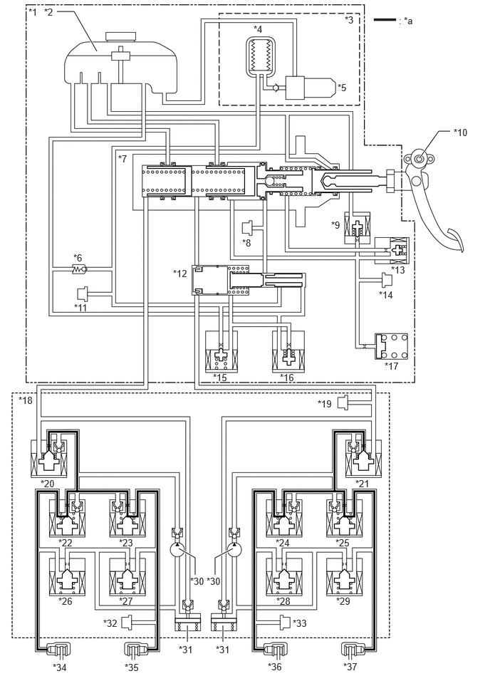
| *1 | Brake Booster with Master Cylinder Assembly | *2 | Brake Master Cylinder Reservoir Assembly |
| *3 | Brake Booster with Accumulator Pump Assembly | *4 | Accumulator |
| *5 | Pump Motor | *6 | Relief Valve |
| *7 | Master Cylinder | *8 | Servo Pressure Sensor (Psrv) |
| *9 | Stroke Simulator Cut Valve (SSA) | *10 | Brake Pedal Stroke Sensor Assembly |
| *11 | Accumulator Pressure Sensor (Pacc) | *12 | Regulator |
| *13 | Gap Hold Valve (SGH) | *14 | Stroke Simulator Pressure Sensor (Prct) |
| *15 | Linear Solenoid Valve (SLA) | *16 | Linear Solenoid Valve (SLR) |
| *17 | Stroke Simulator | *18 | Brake Actuator Assembly |
| *19 | Master Cylinder Pressure Sensor (Pmc) | *20 | Linear Solenoid Valve (SM2) |
| *21 | Linear Solenoid Valve (SM1) | *22 | Pressure Holding Solenoid Valve (SRRH) |
| *23 | Pressure Holding Solenoid Valve (SRLH) | *24 | Pressure Holding Solenoid Valve (SFRH) |
| *25 | Pressure Holding Solenoid Valve (SFLH) | *26 | Pressure Reduction Solenoid Valve (SRRR) |
| *27 | Pressure Reduction Solenoid Valve (SRLR) | *28 | Pressure Reduction Solenoid Valve (SFRR) |
| *29 | Pressure Reduction Solenoid Valve (SFLR) | *30 | Pump |
| *31 | Reservoir | *32 | Wheel Cylinder Pressure Sensor (Pwc2) |
| *33 | Wheel Cylinder Pressure Sensor (Pwc1) | *34 | Rear Brake RH |
| *35 | Rear Brake LH | *36 | Front Brake RH |
| *37 | Front Brake LH | - | - |
| *a | Wheel cylinder pressure (pressure maintained) | - | - |
| Master Cylinder Pressure Control | Not Activate |
| Wheel Cylinder Pressure Control (Linear Solenoid Valve (SM1, SM2)) | Activate |
| Wheel Cylinder Pressure Control (Pressure Holding Solenoid Valve and Pressure Reduction Solenoid Valve) | Not Activate |
Brake Hold
The operation of the solenoid valves under the brake hold is the same as the operation of the hill-start assist control.
Downhill Assist Control
During downhill assist control, the fluid pressure created by the master cylinder in the brake booster assembly (with master cylinder) is sent to the wheel cylinder of each wheel to control the brake fluid pressure so that the tires do not lock while maintaining a set low vehicle speed.
The following illustration shows the operation during pressure increase mode.
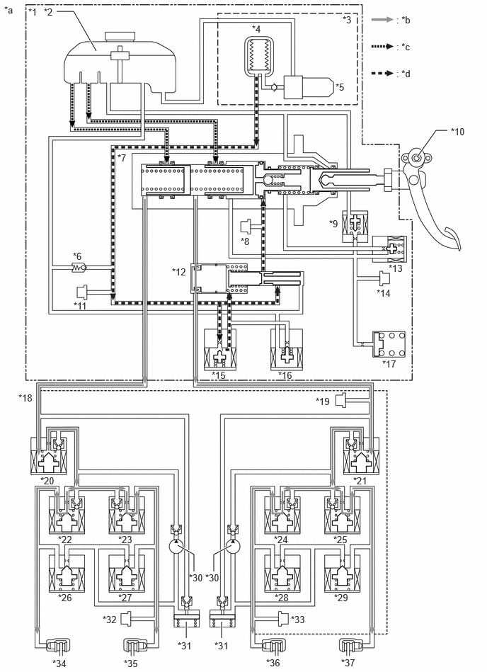
| *1 | Brake Booster with Master Cylinder Assembly | *2 | Brake Master Cylinder Reservoir Assembly |
| *3 | Brake Booster with Accumulator Pump Assembly | *4 | Accumulator |
| *5 | Pump Motor | *6 | Relief Valve |
| *7 | Master Cylinder | *8 | Servo Pressure Sensor (Psrv) |
| *9 | Stroke Simulator Cut Valve (SSA) | *10 | Brake Pedal Stroke Sensor Assembly |
| *11 | Accumulator Pressure Sensor (Pacc) | *12 | Regulator |
| *13 | Gap Hold Valve (SGH) | *14 | Stroke Simulator Pressure Sensor (Prct) |
| *15 | Linear Solenoid Valve (SLA) | *16 | Linear Solenoid Valve (SLR) |
| *17 | Stroke Simulator | *18 | Brake Actuator Assembly |
| *19 | Master Cylinder Pressure Sensor (Pmc) | *20 | Linear Solenoid Valve (SM2) |
| *21 | Linear Solenoid Valve (SM1) | *22 | Pressure Holding Solenoid Valve (SRRH) |
| *23 | Pressure Holding Solenoid Valve (SRLH) | *24 | Pressure Holding Solenoid Valve (SFRH) |
| *25 | Pressure Holding Solenoid Valve (SFLH) | *26 | Pressure Reduction Solenoid Valve (SRRR) |
| *27 | Pressure Reduction Solenoid Valve (SRLR) | *28 | Pressure Reduction Solenoid Valve (SFRR) |
| *29 | Pressure Reduction Solenoid Valve (SFLR) | *30 | Pump |
| *31 | Reservoir | *32 | Wheel Cylinder Pressure Sensor (Pwc2) |
| *33 | Wheel Cylinder Pressure Sensor (Pwc1) | *34 | Rear Brake RH |
| *35 | Rear Brake LH | *36 | Front Brake RH |
| *37 | Front Brake LH | - | - |
| *a | This illustration is an example. | *b | Flow of brake fluid pressurized by the brake booster with master cylinder assembly |
| *c | Flow of brake fluid from the brake master cylinder reservoir assembly | *d | Flow of brake fluid for the servo chamber |
| Master Cylinder Pressure Control | Activate |
| Wheel Cylinder Pressure Control (Linear Solenoid Valve (SM1, SM2)) | Activate |
| Wheel Cylinder Pressure Control (Pressure Holding Solenoid Valve and Pressure Reduction Solenoid Valve) | Activate |
CRAWL
During CRAWL control, the fluid pressure created by the master cylinder in the brake booster assembly (with master cylinder) is sent to the wheel cylinder of each wheel to control brake fluid pressure so that slipping of the driving wheels and wheel locking when driving downhill are suppressed while maintaining a set low vehicle speed.
The following illustration shows the operation during pressure increase mode.
| *1 | Brake Booster with Master Cylinder Assembly | *2 | Brake Master Cylinder Reservoir Assembly |
| *3 | Brake Booster with Accumulator Pump Assembly | *4 | Accumulator |
| *5 | Pump Motor | *6 | Relief Valve |
| *7 | Master Cylinder | *8 | Servo Pressure Sensor (Psrv) |
| *9 | Stroke Simulator Cut Valve (SSA) | *10 | Brake Pedal Stroke Sensor Assembly |
| *11 | Accumulator Pressure Sensor (Pacc) | *12 | Regulator |
| *13 | Gap Hold Valve (SGH) | *14 | Stroke Simulator Pressure Sensor (Prct) |
| *15 | Linear Solenoid Valve (SLA) | *16 | Linear Solenoid Valve (SLR) |
| *17 | Stroke Simulator | *18 | Brake Actuator Assembly |
| *19 | Master Cylinder Pressure Sensor (Pmc) | *20 | Linear Solenoid Valve (SM2) |
| *21 | Linear Solenoid Valve (SM1) | *22 | Pressure Holding Solenoid Valve (SRRH) |
| *23 | Pressure Holding Solenoid Valve (SRLH) | *24 | Pressure Holding Solenoid Valve (SFRH) |
| *25 | Pressure Holding Solenoid Valve (SFLH) | *26 | Pressure Reduction Solenoid Valve (SRRR) |
| *27 | Pressure Reduction Solenoid Valve (SRLR) | *28 | Pressure Reduction Solenoid Valve (SFRR) |
| *29 | Pressure Reduction Solenoid Valve (SFLR) | *30 | Pump |
| *31 | Reservoir | *32 | Wheel Cylinder Pressure Sensor (Pwc2) |
| *33 | Wheel Cylinder Pressure Sensor (Pwc1) | *34 | Rear Brake RH |
| *35 | Rear Brake LH | *36 | Front Brake RH |
| *37 | Front Brake LH | - | - |
| *a | This illustration is an example. | *b | Flow of brake fluid pressurized by the brake booster with master cylinder assembly |
| *c | Flow of brake fluid from the brake master cylinder reservoir assembly | *d | Flow of brake fluid for the servo chamber |
| Master Cylinder Pressure Control | Activate |
| Wheel Cylinder Pressure Control (Linear Solenoid Valve (SM1, SM2)) | Activate |
| Wheel Cylinder Pressure Control (Pressure Holding Solenoid Valve and Pressure Reduction Solenoid Valve) | Activate |
Control during Malfunction of Brake Booster with Master Cylinder Assembly
When the brake master cylinder is malfunctioning, braking force is ensured by the brake actuator using brake fluid pressure generated by the stroke of the brake pedal depressed by the driver.
The following illustration shows the operation during pressure increase mode.
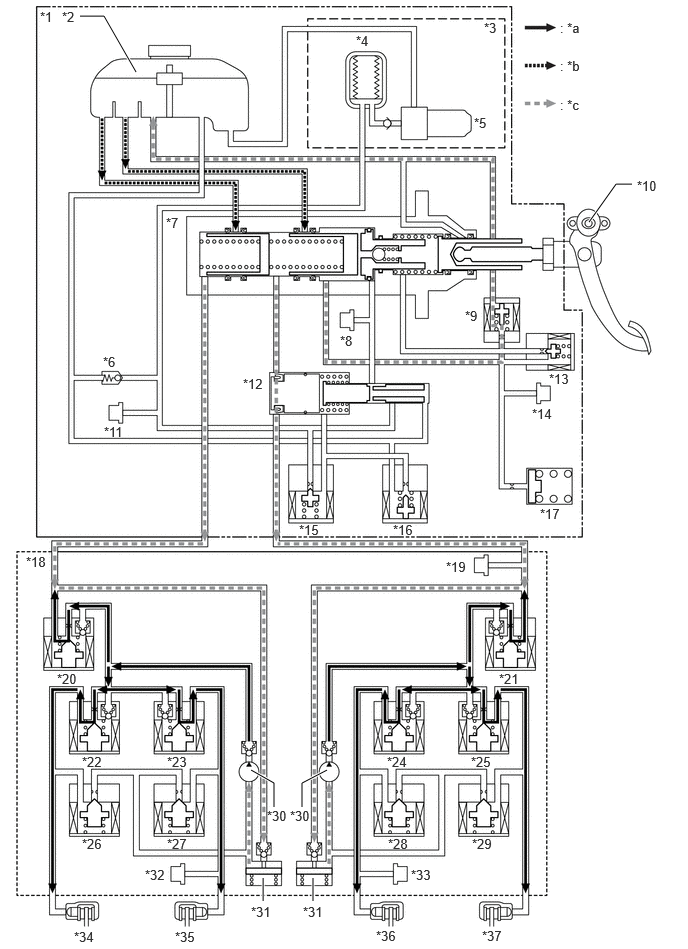
| *1 | Brake Booster with Master Cylinder Assembly | *2 | Brake Master Cylinder Reservoir Assembly |
| *3 | Brake Booster with Accumulator Pump Assembly | *4 | Accumulator |
| *5 | Pump Motor | *6 | Relief Valve |
| *7 | Master Cylinder | *8 | Servo Pressure Sensor (Psrv) |
| *9 | Stroke Simulator Cut Valve (SSA) | *10 | Brake Pedal Stroke Sensor Assembly |
| *11 | Accumulator Pressure Sensor (Pacc) | *12 | Regulator |
| *13 | Gap Hold Valve (SGH) | *14 | Stroke Simulator Pressure Sensor (Prct) |
| *15 | Linear Solenoid Valve (SLA) | *16 | Linear Solenoid Valve (SLR) |
| *17 | Stroke Simulator | *18 | Brake Actuator Assembly |
| *19 | Master Cylinder Pressure Sensor (Pmc) | *20 | Linear Solenoid Valve (SM2) |
| *21 | Linear Solenoid Valve (SM1) | *22 | Pressure Holding Solenoid Valve (SRRH) |
| *23 | Pressure Holding Solenoid Valve (SRLH) | *24 | Pressure Holding Solenoid Valve (SFRH) |
| *25 | Pressure Holding Solenoid Valve (SFLH) | *26 | Pressure Reduction Solenoid Valve (SRRR) |
| *27 | Pressure Reduction Solenoid Valve (SRLR) | *28 | Pressure Reduction Solenoid Valve (SFRR) |
| *29 | Pressure Reduction Solenoid Valve (SFLR) | *30 | Pump |
| *31 | Reservoir | *32 | Wheel Cylinder Pressure Sensor (Pwc2) |
| *33 | Wheel Cylinder Pressure Sensor (Pwc1) | *34 | Rear Brake RH |
| *35 | Rear Brake LH | *36 | Front Brake RH |
| *37 | Front Brake LH | - | - |
| *a | Flow of brake fluid pressurized by the brake actuator assembly | *b | Flow of brake fluid from the brake master cylinder reservoir assembly |
| *c | Flow of brake fluid by pressure generated by brake pedal operation | - | - |
| Master Cylinder Pressure Control | Malfunction |
| Wheel Cylinder Pressure Control (Linear Solenoid Valve (SM1, SM2)) | Activate |
| Wheel Cylinder Pressure Control (Pressure Holding Solenoid Valve and Pressure Reduction Solenoid Valve) | Not Activate |
Control during Brake Actuator Assembly Malfunction
When there is a malfunction in the brake actuator assembly, the stroke simulator cut valve (SSA) closes and the gap hold valve (SGH) opens. At this time, the brake fluid pressure generated by the brake booster with master cylinder assembly is supplied to each wheel cylinder and the increase in pressure is adjusted.
The following illustration shows the operation during pressure increase mode.
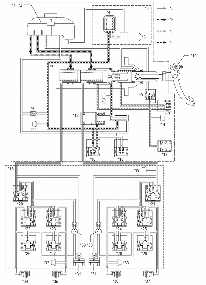
| *1 | Brake Booster with Master Cylinder Assembly | *2 | Brake Master Cylinder Reservoir Assembly |
| *3 | Brake Booster with Accumulator Pump Assembly | *4 | Accumulator |
| *5 | Pump Motor | *6 | Relief Valve |
| *7 | Master Cylinder | *8 | Servo Pressure Sensor (Psrv) |
| *9 | Stroke Simulator Cut Valve (SSA) | *10 | Brake Pedal Stroke Sensor Assembly |
| *11 | Accumulator Pressure Sensor (Pacc) | *12 | Regulator |
| *13 | Gap Hold Valve (SGH) | *14 | Stroke Simulator Pressure Sensor (Prct) |
| *15 | Linear Solenoid Valve (SLA) | *16 | Linear Solenoid Valve (SLR) |
| *17 | Stroke Simulator | *18 | Brake Actuator Assembly |
| *19 | Master Cylinder Pressure Sensor (Pmc) | *20 | Linear Solenoid Valve (SM2) |
| *21 | Linear Solenoid Valve (SM1) | *22 | Pressure Holding Solenoid Valve (SRRH) |
| *23 | Pressure Holding Solenoid Valve (SRLH) | *24 | Pressure Holding Solenoid Valve (SFRH) |
| *25 | Pressure Holding Solenoid Valve (SFLH) | *26 | Pressure Reduction Solenoid Valve (SRRR) |
| *27 | Pressure Reduction Solenoid Valve (SRLR) | *28 | Pressure Reduction Solenoid Valve (SFRR) |
| *29 | Pressure Reduction Solenoid Valve (SFLR) | *30 | Pump |
| *31 | Reservoir | *32 | Wheel Cylinder Pressure Sensor (Pwc2) |
| *33 | Wheel Cylinder Pressure Sensor (Pwc1) | *34 | Rear Brake RH |
| *35 | Rear Brake LH | *36 | Front Brake RH |
| *37 | Front Brake LH | - | - |
| *a | Flow of brake fluid pressurized by the brake booster with master cylinder assembly | *b | Flow of brake fluid from the brake master cylinder reservoir assembly |
| *c | Flow of brake fluid by pressure generated by brake pedal operation | *d | Flow of brake fluid for the servo chamber |
| Master Cylinder Pressure Control | Activate |
| Wheel Cylinder Pressure Control (Linear Solenoid Valve (SM1, SM2)) | Malfunction |
| Wheel Cylinder Pressure Control (Pressure Holding Solenoid Valve and Pressure Reduction Solenoid Valve) | Malfunction |
Control during Malfunction in One Circuit
The stroke simulator cut valve (SSA) is closed and the gap hold valve (SGH) is opened. At this time, brake fluid pressure generated by the brake booster with master cylinder assembly is directed to the correctly functioning wheel cylinders and the system operates another circuit.
The following illustration shows the operation during brake fluid pressure increase due to the front circuit malfunction.
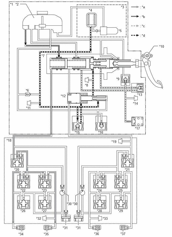
| *1 | Brake Booster with Master Cylinder Assembly | *2 | Brake Master Cylinder Reservoir Assembly |
| *3 | Brake Booster with Accumulator Pump Assembly | *4 | Accumulator |
| *5 | Pump Motor | *6 | Relief Valve |
| *7 | Master Cylinder | *8 | Servo Pressure Sensor (Psrv) |
| *9 | Stroke Simulator Cut Valve (SSA) | *10 | Brake Pedal Stroke Sensor Assembly |
| *11 | Accumulator Pressure Sensor (Pacc) | *12 | Regulator |
| *13 | Gap Hold Valve (SGH) | *14 | Stroke Simulator Pressure Sensor (Prct) |
| *15 | Linear Solenoid Valve (SLA) | *16 | Linear Solenoid Valve (SLR) |
| *17 | Stroke Simulator | *18 | Brake Actuator Assembly |
| *19 | Master Cylinder Pressure Sensor (Pmc) | *20 | Linear Solenoid Valve (SM2) |
| *21 | Linear Solenoid Valve (SM1) | *22 | Pressure Holding Solenoid Valve (SRRH) |
| *23 | Pressure Holding Solenoid Valve (SRLH) | *24 | Pressure Holding Solenoid Valve (SFRH) |
| *25 | Pressure Holding Solenoid Valve (SFLH) | *26 | Pressure Reduction Solenoid Valve (SRRR) |
| *27 | Pressure Reduction Solenoid Valve (SRLR) | *28 | Pressure Reduction Solenoid Valve (SFRR) |
| *29 | Pressure Reduction Solenoid Valve (SFLR) | *30 | Pump |
| *31 | Reservoir | *32 | Wheel Cylinder Pressure Sensor (Pwc2) |
| *33 | Wheel Cylinder Pressure Sensor (Pwc1) | *34 | Rear Brake RH |
| *35 | Rear Brake LH | *36 | Front Brake RH |
| *37 | Front Brake LH | - | - |
| *a | Flow of brake fluid pressurized by the brake booster with master cylinder assembly | *b | Flow of brake fluid from the brake master cylinder reservoir assembly |
| *c | Flow of brake fluid by pressure generated by brake pedal operation | *d | Flow of brake fluid for the servo chamber |
| Master Cylinder Pressure Control | Activate |
| Wheel Cylinder Pressure Control (Linear Solenoid Valve (SM1, SM2)) | Activate |
| Wheel Cylinder Pressure Control (Pressure Holding Solenoid Valve and Pressure Reduction Solenoid Valve) | Not Activate |
Control Operation during Power Supply Malfunction
The stroke simulator cut valve (SSA) is opened and the gap hold valve (SGH) is closed. Accordingly, the brake fluid pressure generated by the brake booster with master cylinder assembly from the force applied to the brake pedal by the driver is supplied to each wheel cylinder.
The following illustration shows the operation during pressure increase mode.
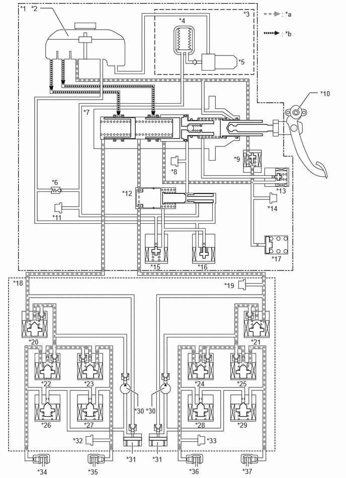
| *1 | Brake Booster with Master Cylinder Assembly | *2 | Brake Master Cylinder Reservoir Assembly |
| *3 | Brake Booster with Accumulator Pump Assembly | *4 | Accumulator |
| *5 | Pump Motor | *6 | Relief Valve |
| *7 | Master Cylinder | *8 | Servo Pressure Sensor (Psrv) |
| *9 | Stroke Simulator Cut Valve (SSA) | *10 | Brake Pedal Stroke Sensor Assembly |
| *11 | Accumulator Pressure Sensor (Pacc) | *12 | Regulator |
| *13 | Gap Hold Valve (SGH) | *14 | Stroke Simulator Pressure Sensor (Prct) |
| *15 | Linear Solenoid Valve (SLA) | *16 | Linear Solenoid Valve (SLR) |
| *17 | Stroke Simulator | *18 | Brake Actuator Assembly |
| *19 | Master Cylinder Pressure Sensor (Pmc) | *20 | Linear Solenoid Valve (SM2) |
| *21 | Linear Solenoid Valve (SM1) | *22 | Pressure Holding Solenoid Valve (SRRH) |
| *23 | Pressure Holding Solenoid Valve (SRLH) | *24 | Pressure Holding Solenoid Valve (SFRH) |
| *25 | Pressure Holding Solenoid Valve (SFLH) | *26 | Pressure Reduction Solenoid Valve (SRRR) |
| *27 | Pressure Reduction Solenoid Valve (SRLR) | *28 | Pressure Reduction Solenoid Valve (SFRR) |
| *29 | Pressure Reduction Solenoid Valve (SFLR) | *30 | Pump |
| *31 | Reservoir | *32 | Wheel Cylinder Pressure Sensor (Pwc2) |
| *33 | Wheel Cylinder Pressure Sensor (Pwc1) | *34 | Rear Brake RH |
| *35 | Rear Brake LH | *36 | Front Brake RH |
| *37 | Front Brake LH | - | - |
| *a | Flow of brake fluid by pressure generated by brake pedal operation | *b | Flow of brake fluid from the brake master cylinder reservoir assembly |
| Master Cylinder Pressure Control | Malfunction |
| Wheel Cylinder Pressure Control (Linear Solenoid Valve (SM1, SM2)) | Activate |
| Wheel Cylinder Pressure Control (Pressure Holding Solenoid Valve and Pressure Reduction Solenoid Valve) | Not Activate |