HEATING / AIR CONDITIONING AIR CONDITIONING SYSTEM DETAILS COOL BOX
COOLING BOX
General
The cooling box is available in the center console box as an option.
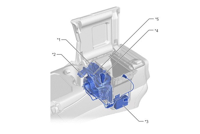
| *1 | No. 2 Cooler Evaporator Sub-assembly | *2 | Cooling Box Blower with Fan Motor Sub-assembly |
| *3 | Air Conditioning Amplifire Assembly (for Cool Box) | *4 | Control Switch Assembly |
| *5 | No. 3 Cooler Thermistor | - | - |
The cooling box employs a method of a continuous refrigerant flow control, which regulates the refrigerant flow through the ejector located in the refrigerant pipes, thereby ensuring high air conditioning performance and cooling efficiency.
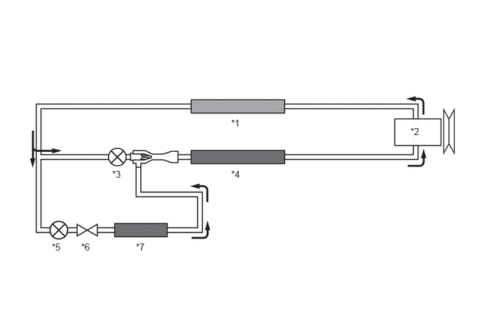
| *1 | Condenser | *2 | Compressor |
| *3 | Cooler Expansion Valve | *4 | Evaporator (for Front Air Conditioning Unit) |
| *5 | Fixed Squeezing Valve | *6 | Magnetic Valve |
| *7 | Evaporator (for Cooling Box) | - | - |
Ejector
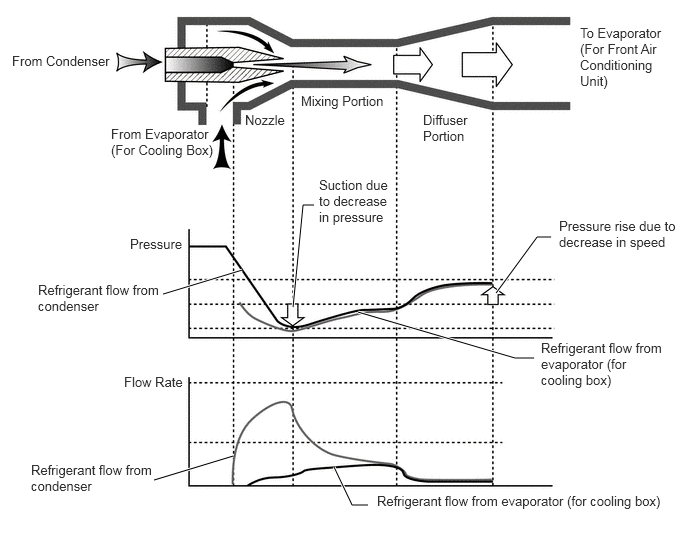
The ejector includes nozzle, mixing and diffuser portions.
A high temperature, high pressure liquid refrigerant flowing from the condenser is guided into the mixing portion through the nozzle portion at high speed as the nozzle is inwardly tapered. This tapered nozzle allows the refrigerant pressure in the vicinity of the nozzle to decrease while guiding a low temperature, low pressure gaseous refrigerant into the nozzle portion from the evaporator (for cooling box). Thus, both refrigerants are mixed in the mixing portion and then sent to the diffuser portion.
As the diffuser section is outwardly flared, the refrigerant flow rate in the diffuser decreases and the refrigerant pressure rises.
Under this operational mechanism, the refrigerant pressure in the cooling box can be kept lower than in the front air conditioning unit even if refrigerant is continuously flowing, moreover, the refrigerant can be kept at a low temperature, thereby achieving high cooling efficiency and air conditioning performance.
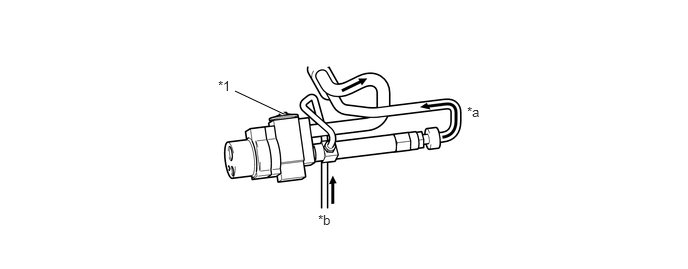
| *1 | Cooler Expansion Valve | - | - |
| *a | to Evaporator | *b | from Cooling Box |