Home › Vehicle Exterior › EXTERIOR PANELS / TRIM › BODY STRUCTURE
NM38G0E _59 Vehicle Exterior _101137 EXTERIOR PANELS / TRIM _0480056 BODY STRUCTURE DE DETAILS F

EXTERIOR PANELS / TRIM  BODY STRUCTURE  DETAILS  AERODYNAMICS  


CONSTRUCTION


a.

Aero Stabilizing Fin

i.

An aero stabilizing fin is provided in the front door front lower frame cover upper. The air flowing over the aero stabilizing fin generates spiral turbulence behind the fin. This turbulence suppresses air separation from the side of the body, reduces air resistance (the resistance due to the negative pressure that occurs behind physical objects) and laterally presses against the vehicle to ensure superior driving stability.


ii.

The front door outside handle assembly and rear door outside handle assembly are given shapes with the same feature as the aero stabilizing fin.
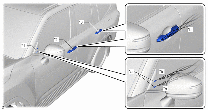
V130387C01
0.917,1.583 1.083,1.583 1.083,1.583 1.25,1.75 true 2.021,1.375 2.188,1.375 2.188,1.375 2.521,1.708 true 2.885,0.771 3.052,0.771 3.052,0.771 3.385,1.104 true 5.313,3.01 4.635,2.479 4.635,2.479 5.292,2.813 true 0.74,1.5 0.917,1.667 0.177,0.167 10 true *1 1.854,1.292 2.031,1.448 0.177,0.156 10 true *2 2.719,0.688 2.885,0.844 0.167,0.156 10 true *3 4.438,2.396 4.604,2.552 0.167,0.156 10 true *a 6.469,0.938 6.646,1.104 0.177,0.167 10 true *b 5.49,2.396 5.667,2.563 0.177,0.167 10 true *b 5.625,2.99 5.802,3.156 0.177,0.167 10 true *b
*1 Front Door Front Lower Frame Cover Upper *2 Front Door Outside Handle Assembly
*3 Rear Door Outside Handle Assembly - -
*a Aero Stabilizing Fin *b Turbulence


b.

Under Cover

i.

By flattening the underfloor with an undercover, the air flowing under the vehicle is rectified, improving steering stability and fuel efficiency.
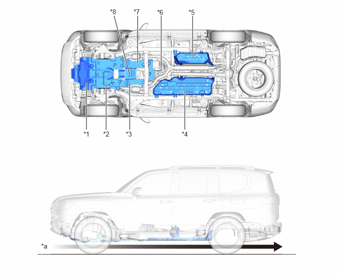
V130388C01
4.083,1.167 4.083,0.333 true 3.917,2.75 3.917,1.917 true 2.75,2.75 2.75,1.75 true 3.25,1.5 3.417,1.5 3.417,1.5 3.417,0.333 true 2.917,1.333 2.917,0.333 true 2.75,1.583 2.417,0.333 true 2.25,2.75 2.25,1.75 true 1.833,2.75 1.833,1.75 true 1.771,2.76 2.083,2.917 0.313,0.156 10 false *1 2.188,2.76 2.5,2.917 0.313,0.156 10 false *2 2.667,2.76 2.979,2.917 0.313,0.156 10 false *3 3.854,2.76 4.167,2.917 0.313,0.156 10 false *4 4,0.177 4.313,0.333 0.313,0.156 10 false *5 3.333,0.177 3.646,0.333 0.313,0.156 10 false *6 2.833,0.167 3.146,0.323 0.313,0.156 10 false *7 2.333,0.167 2.646,0.323 0.313,0.156 10 false *8 0.875,5.135 1.188,5.292 0.313,0.156 10 false *a
*1 NO. 1 Engine Under Cover Assembly *2 NO. 2 Engine Under Cover Assembly
*3 Frame Under Cover Assembly RH *4 NO. 1 Fuel Tank Protector Sub-assembly
*5 NO. 2 Fuel Tank Protector *6 Transmission Under Cover Assembly
*7 Frame Under Cover Assembly LH *8 Oil Pan Protector Assembly
*a Air Flow Image - -


c.

Rear End

i.

An rear spoiler sub-assembly is used. As a result, the airflow from the roof and cabin side is directed to the rear, suppressing air turbulence at the rear of the vehicle and decreasing air resistance.
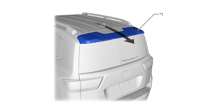
Rear End (This illustration is an example only.)
V130389C01
4.833,1.083 5.417,0.5 5.417,0.5 5.583,0.5 true 5.604,0.427 5.917,0.583 0.313,0.156 10 false *1
*1 Rear Spoiler Sub-assembly - -
V100135

Airflow - -


d.

Wheel House Liner

i.

Beads are provided to free the high-pressure turbulence outward that causes air resistance in the wheelhouse by the rotation of the tires.
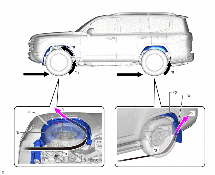
V130390C01
0.667,4.417 2.083,4.417 2.083,4.417 2.083,4.125 true 1.875,4.417 1.875,4.125 true 1.583,4.167 1.167,3.75 1.167,3.75 1.083,3.75 true 5.646,3.802 5.646,3.073 5.646,3.073 5.729,3.073 true 5.948,4.104 6.094,3.167 6.094,3.167 6.177,3.167 true 2.375,1.479 2.583,1.656 0.208,0.177 10 true *a 2.104,5.042 2.271,5.208 0.167,0.167 10 true *a 6.333,3.708 6.49,3.865 0.156,0.156 10 true *c 0.51,4.323 0.844,4.479 0.333,0.156 10 false *b 2.063,3.563 2.375,3.719 0.313,0.156 10 false *c 5.115,4.917 5.427,5.073 0.313,0.156 10 false *a 6.208,3.094 6.521,3.25 0.313,0.156 10 false *b 2.5,2.333 2.813,2.49 0.313,0.156 10 false *a 5.677,2.313 5.99,2.469 0.313,0.156 10 false *a 0.938,3.677 1.25,3.833 0.313,0.156 10 false *1 5.771,3.01 6.083,3.167 0.313,0.156 10 false *2
*1 Fender Splash Shield Sub-assembly *2 Rear Wheel House Liner
*a Airflow Caused by Tire Rotation *b Bead
*c Air Introduction by Bead - -


e.

Air Spats

i.

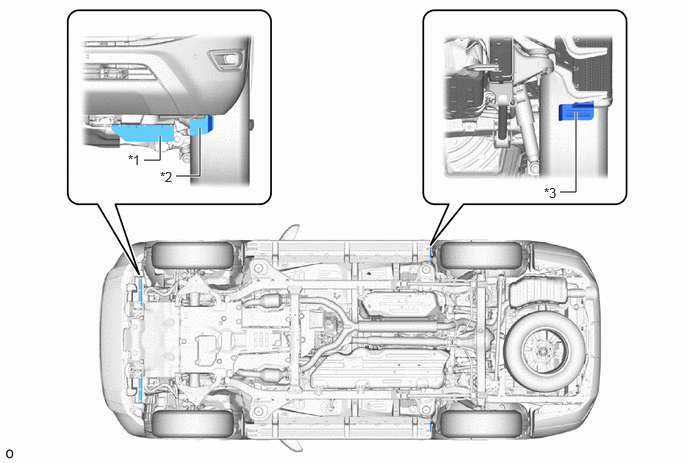
A engine side cover sub-assembly, front wheel opening extension pad and rear step panel are provided in front of the front and rear tires to adjust the air flowing under the vehicle.
Air Spats (This illustration is an example only.)
V130391C01
1.5,1.667 1.667,1.667 1.667,1.667 1.667,1.417 true 6,1.167 6,2 6,2 5.833,2 true 1.833,1.833 2.083,1.833 2.083,1.833 2.083,1.333 true 1.333,1.583 1.531,1.719 0.198,0.135 10 false *1 1.667,1.76 1.917,1.917 0.25,0.156 10 false *2 5.667,1.927 5.917,2.083 0.25,0.156 10 false *3
*1 Engine Side Cover Sub-assembly *2 Front Wheel Opening Extension Pad
*3 Rear Step Panel - -


f.

Rear Mad Guard

i.

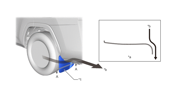
A cylindrical shape has been added to the conventional mudguard shape to achieve both mud receiving performance and aerodynamic performance.
V130392C01
4.125,0.844 6.688,2.573 2.563,1.729 3.25,3.333 3.083,3.333 3.083,3.333 2.667,2.917 true 2.333,3.125 2.646,3.281 0.313,0.156 10 false A 4.323,2.833 4.635,2.99 0.313,0.156 10 false *b 3.125,2.813 3.438,2.969 0.313,0.156 10 false A 5.333,2.302 5.646,2.458 0.313,0.156 10 false *a 6.146,1.01 6.458,1.167 0.313,0.156 10 false *b 3.271,3.25 3.583,3.406 0.313,0.156 10 false *1
*1 Rear Quater Panel Mudguard - -
*a A - A Cross Sectionl *b Airflow