POWER DISTRIBUTION POWER INTEGRATION SYSTEM CONTROL POWER SOURCE CONTROL
FUNCTION OF MAIN COMPONENTS
| Components | Function |
|---|---|
| No. 1 Engine Room Relay Block
·
IGP Relay |
Turns the power supply to the drive force system on and off. |
| Power Distribution Box Assembly
·
IGR Relay |
·
Contains a built-in IGR relay and turns the power supply to other systems on and off.
·
Sends message display request signals to the combination meter assembly.
·
Sends power off request signals to the certification ECU.
·
Receives power source management control request signals from the ECM and restricts operations such as heater system loads. |
| Engine Switch (Push Start Switch) | A switch for turning on the power source and starting the engine. |
| Battery State Sensor Assembly | Detects the auxiliary battery capacity and sends the information to the ECM. |
| Certification ECU (Smart Key ECU Assembly) | Receives power off request signals from the power distribution box assembly and controls the operations of the IGP relay and IGR relay. |
| Main Body ECU (Multiplex Network Body ECU) | Relays the signals to the power distribution box assembly. |
| Brake Actuator Assembly
·
No. 2 Skid Control ECU |
Sends the vehicle speed signal to the certification ECU. |
| Air Conditioning Amplifier Assembly | Receives auxiliary battery capacity signals from the ECM and restricts operations such as heater system loads. |
| ECM | Sends auxiliary battery capacity signals to the power distribution box assembly or air conditioning amplifier assembly based on the auxiliary battery status. |
| Combination Meter Assembly | Displays a message on the multi-information display when a malfunction occurs. |
| Central Gateway ECU (Network Gateway ECU) | Relays the signal between the CAN communication lines. |
| DLC3 | Can read the Diagnostic Trouble Codes (DTCs) of malfunctions by connecting the Global TechStream (GTS). |
FUNCTION
Scene-based Power Supply System
An IGP relay supplying power to the drive force system and an IGR relay supplying power to the other systems are provided, and the power supply to each system is controlled by operating the IGP relay and IGR relay according to the conditions.
In the "Emergency stop while driving" condition, only the power supply to the drive force system is stopped, while the power continues to be supplied to the other systems until the vehicle is stopped.
- NOTICE:
-
·
This does not guarantee the operation of each system until the vehicle is stopped.
·Since a system may stop operation before the vehicle is stopped depending on the remaining power in the auxiliary battery or how the battery is used, do not operate the emergency stop except in an actual emergency.
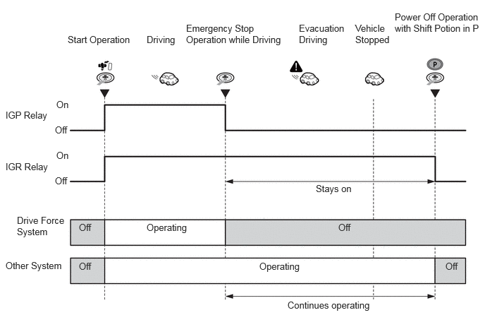
Power Source Management Control
A power source management control is divided into control while driving and control while the vehicle is stopped.
Power Source Management while Driving
When any of the following conditions occurs while driving, the target electrical loads are stopped and assistance in securing electric power is provided until the retreat is made.
When a malfunction occurs in the auxiliary battery charging system (low voltage request)
When an emergency stop is operated
| Stop Target Electrical Load | At Low Voltage Request | At Emergency Stop Operation | |
|---|---|---|---|
|
*1: Models with PTC heater *2: Models with seat heater system *3: Models with climate control seat system *4: Models with windshield deicer system *5: Models with windshield deicer system *6: Models with windshield deicer system *7: Models with heated windshield defroster system |
|||
| PTC Heater*1 | OFF | OFF | |
| Seat Heater System*2 | OFF | OFF | |
| Climate Control Seat System*3 | OFF | OFF | |
| Heated Steering Wheel System*4 | OFF | OFF | |
| Rear Window Defogger System | OFF | OFF | |
| Mirror Heater*5 | OFF | OFF | |
| Windshield Deicer System*6 | OFF | OFF | |
| Heated Windshield Defroster System*7 | OFF | OFF | |
| Air Conditioning Blower Motor | Defroster Off | Low Request | Low Request |
| Defroster On | Normal Operation | Normal Operation | |
During a low voltage request for the auxiliary battery, a message is displayed on the multi-information display of the combination meter assembly to urge the driver to stop the vehicle.
Power Source Management while Vehicle Stopped
When any of the following conditions occurs while the vehicle is stopped, the power source turns off automatically to reduce battery depletion.
W hen the power source position on (IG or ACC) continues for a certain period of time (approximately 20 minutes)
When the power source position on (IG or ACC) and auxiliary battery capacity below a certain value (approximately 30%) continues for a certain period of time (approximately 4 minutes)
- HINT:
-
When turning the engine switch on (IG) after the power source turned off due to low auxiliary battery capacity, the power source off operation due to low battery capacity is not performed.
When low auxiliary battery capacity is detected, a message is displayed on the multi-information display of the combination meter assembly to urge the driver to turn the power source off.
FAIL-SAFE
When a malfunction occurs in the battery state sensor assembly, the engine switch off request due to low auxiliary battery capacity is stopped to prevent the power source from turning off unnecessarily.