Home › Engine / Hybrid System › F33A-FTV (FUEL) › FUEL SYSTEM › from 2021.07
NM38G0E _51 Engine / Hybrid System _106496 F33A-FTV FUEL _0487133 FUEL SYSTEM DE DETAILS F

F33A-FTV FUEL  FUEL SYSTEM  DETAILS  FUEL FILTER  


CONSTRUCTION


a.

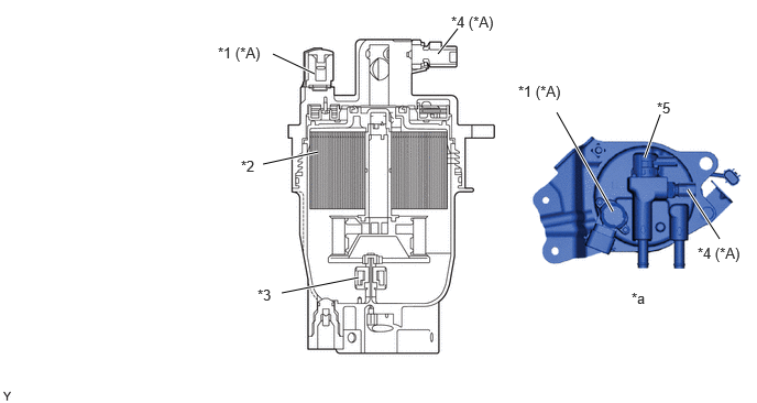
A fuel filter assembly consists of a separate filter element and a filter housing.


b.

A paper filter element that offers high filtering efficiency and captures the particles is used.


c.

A fuel filter warning switch is provided in the fuel filter assembly.


d.

A fuel heater is used.*

*: Models with fuel heater

W148440C02
2.583,0.51 2.979,0.698 true 2.667,2.771 3.396,2.625 true 4.146,0.51 4.333,0.271 true 2.49,1.552 3.01,1.438 true 6.104,1.49 6.25,1.083 true 6.813,2.26 6.51,1.792 true 5.802,2 5.271,1.063 true 2.063,0.417 2.667,0.625 0.604,0.208 10 false *1 (*A) 2.281,1.49 2.594,1.646 0.313,0.156 10 false *2 2.438,2.708 2.75,2.865 0.313,0.156 10 false *3 4.271,0.125 4.875,0.333 0.604,0.208 10 false *4 (*A) 6.219,0.938 6.531,1.094 0.313,0.156 10 false *5 6.604,2.313 7.094,2.51 0.49,0.198 10 false *4 (*A) 5.979,2.74 6.292,2.896 0.313,0.156 10 false *a 4.906,0.781 5.51,0.99 0.604,0.208 10 false *1 (*A)
*A Models with Fuel Heater - -
*1 Fuel Heater *2 Fuel Filter Element Sub-assembly
*3 Fuel Sedimenter Level Warning Switch *4 Fuel Temperature Sensor
*5 Fuel Filter Warning Switch (Vacuum Switch) - -
*a Top Side View - -


OPERATION


a.

Warning Ligtht

i.

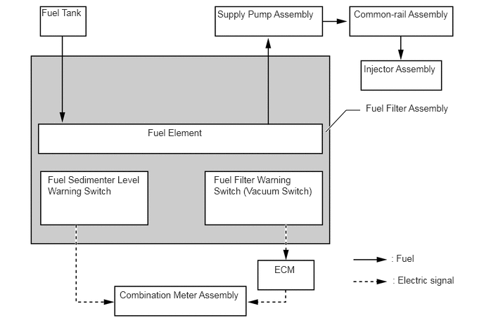
When the water level inside the fuel filter assembly reaches the specified level or higher, the fuel sediment level warning switch turns on, the master warning light in the combination meter assembly is illuminated, a warning message is displayed on the multi-information display and the multi buzzer is sounded. For details, see the METER / GAUGE / DISPLAY section.


ii.

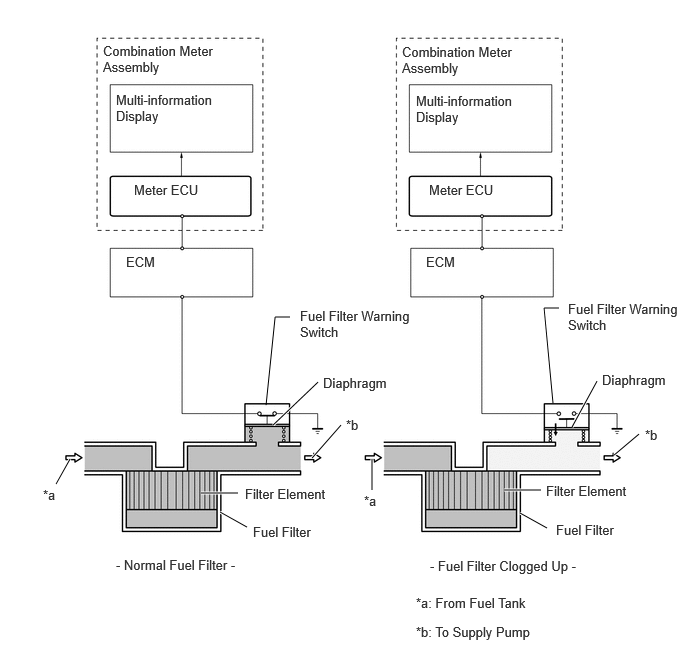
A fuel filter warning switch, which turns on or off when the internal vacuum of the filter increases, is provided in the fuel filter. This switch, which turns off when the internal vacuum of the fuel filter increases to a predetermined level, is connected by wire to the combination meter assembly.
W132327E01
4.823,1.958 5.125,1.635 5.125,1.635 5.333,1.635 true 0.615,0.104 1.292,0.51 0.677,0.406 10 false Fuel Tank 3.219,0.125 4.74,0.542 1.521,0.417 10 false Supply Pump Assembly 5.24,0.125 6.76,0.542 1.521,0.417 10 false Common-rail Assembly 5.385,0.938 6.573,1.323 1.188,0.385 10 false Injector Assembly 2.188,1.885 3.375,2.271 1.188,0.385 10 false Fuel Element 0.708,2.583 2.083,3.323 1.375,0.74 10 false Fuel Sedimenter Level Warning Switch 3.167,2.583 4.677,3.354 1.51,0.771 10 false Fuel Filter Warning Switch (Vacuum Switch) 1.771,4.292 3.656,4.688 1.885,0.396 10 false Combination Meter Assembly 4.063,3.917 4.583,4.25 0.521,0.333 10 false ECM 5.792,3.75 6.313,4.083 0.521,0.333 10 false : Fuel 5.813,4.073 6.865,4.427 1.052,0.354 10 false : Electric signal 5.417,1.521 6.833,1.927 1.417,0.406 10 false Fuel Filter Assembly


iii.

When the combination meter assembly detects via the fuel filter warning switch that the negative pressure inside the fuel filter has increased, it determines that the fuel filter assembly is clogged. It then urges the driver to replace the fuel filter, by illuminating the master warning light in the combination meter assembly and displaying a warning message on the multi-information display. For details, see the METER / GAUGE / DISPLAY section.
W138018E03
2.771,4.219 2.865,3.302 2.865,3.302 3.021,3.302 false 3.313,3.979 2.844,4.427 true 5.76,4.198 5.667,3.208 5.667,3.208 5.823,3.208 false 6.219,3.969 5.958,4.448 true 5.635,5.104 5.25,5.104 true 5.698,5.5 5.417,5.344 true 2.479,5.135 2.094,5.135 true 2.573,5.49 2.292,5.333 true 0.729,4.781 0.583,5.042 true 3.552,4.427 3.25,4.771 true 3.875,4.781 3.875,5.104 true 6.396,4.74 6.656,4.521 true 1.073,0.448 2.74,0.885 1.667,0.438 10 false Combination Meter Assembly 4.188,0.458 5.76,0.875 1.573,0.417 10 false Combination Meter Assembly 1.208,0.958 2.594,1.313 1.385,0.354 10 false Multi-information Display 4.333,0.969 5.719,1.323 1.385,0.354 10 false Multi-information Display 4.469,1.896 5.563,2.125 1.094,0.229 10 false Meter ECU 1.396,1.896 2.49,2.125 1.094,0.229 10 false Meter ECU 3.125,3.208 4.448,3.531 1.323,0.323 10 false Fuel Filter Warning Switch 5.917,3.135 7.115,3.5 1.198,0.365 10 false Fuel Filter Warning Switch 1.313,2.646 2.521,2.969 1.208,0.323 10 false ECM 4.438,2.646 5.646,2.969 1.208,0.323 10 false ECM 3.365,3.906 4.104,4.104 0.74,0.198 10 false Diaphragm 6.271,3.875 7.01,4.073 0.74,0.198 10 false Diaphragm 2.552,5.063 3.813,5.281 1.26,0.219 10 false Filter Element 5.688,5.031 6.948,5.25 1.26,0.219 10 false Filter Element 5.792,5.438 6.906,5.708 1.115,0.271 10 false Fuel Filter 2.635,5.458 3.75,5.729 1.115,0.271 10 false Fuel Filter 0.448,5.073 0.708,5.271 0.26,0.198 10 false *a 3.604,4.344 3.865,4.542 0.26,0.198 10 false *b 3.792,5.135 4.052,5.333 0.26,0.198 10 false *a 6.719,4.448 6.979,4.646 0.26,0.198 10 false *b 4.333,6.198 6.385,6.406 2.052,0.208 10 false *a: From Fuel Tank 4.333,6.5 6.99,6.75 2.656,0.25 10 false *b: To Supply Pump 1.208,5.802 2.833,6.01 1.625,0.208 10 false - Normal Fuel Filter - 4.479,5.813 6.458,6.052 1.979,0.24 10 false - Fuel Filter Clogged Up -


b.

Fuel Heater

i.

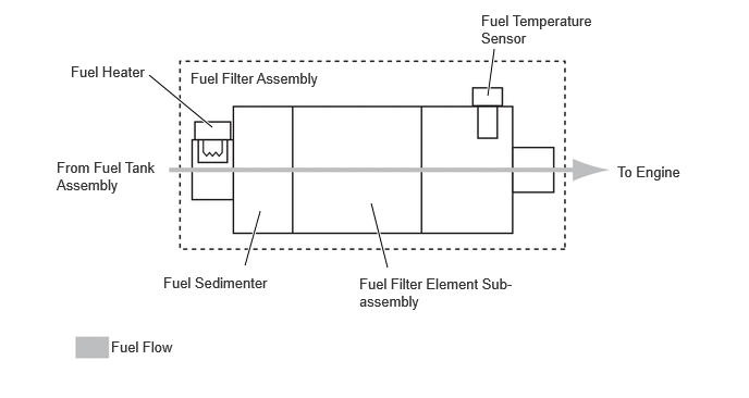
When the fuel temperature sensor detects that the fuel temperature is the specified value or lower, the fuel heater operates and directly warms the fuel.


ii.

The flow of fuel flowing through the fuel heater is as follows:
W148445E02
4.667,0.917 4.729,0.469 true 2.031,1.219 1.427,0.719 true 3.708,2.563 3.552,1.948 true 2.344,2.542 2.49,2.021 true 1.823,0.667 3.313,0.958 1.49,0.292 10 false Fuel Filter Assembly 4.604,0.115 5.781,0.542 1.177,0.427 10 false Fuel Temperature Sensor 1.563,2.625 2.74,2.979 1.177,0.354 10 false Fuel Sedimenter 3.438,2.635 5.031,2.99 1.594,0.354 10 false Fuel Filter Element Sub-assembly 1.063,3.24 2.188,3.469 1.125,0.229 10 false Fuel Flow 5.906,1.563 6.646,1.792 0.74,0.229 10 false To Engine 0.542,1.521 1.573,1.896 1.031,0.375 10 false From Fuel Tank Assembly 0.677,0.604 2.167,0.896 1.49,0.292 10 false Fuel Heater