F33A-FTV ENGINE CONTROL ECD SYSTEM CONTROL intelligent-ACCURACY REFINEMENT TECHNOLOGY (i-ART)
FUNCTION
The ECM precisely controls fuel injection based on signals from the fuel pressure and fuel temperature sensors which are built into each injector assembly. In addition, fuel injector assembly malfunctions can be determined by directly detecting the fuel pressure of the each injector assembly.
Closed loop control is used, thus achieving automatic correction of injection characteristics throughout the entire lifespan of the injector assembly.
OPERATION
Each injector detects both the fuel pressure under the following conditions and the fuel temperature using its own built-in fuel temperature and fuel pressure sensors. The injector gives these values as feedback to the ECM.
When there is no injection
When electrical current starts to flow
When injection starts
When the maximum injection rate has been reached
When electrical current flow has stopped
When the injection rate has been reduced
When injection has stopped
The ECM optimally controls the fuel injection volume based on the feedback values. In addition, fuel injection volume differences between each cylinder are suppressed by directly detecting the injection pressure of each cylinder.
By detecting abnormal levels of fuel pressure under each condition, the ECM also determines the occurrence of abnormalities such as non-injection of the injector assembly, constant injection or fuel leakage.
The injector assembly is provided with an auto-learning function. Learned values are stored by the injector assembly in its own built-in memory IC.
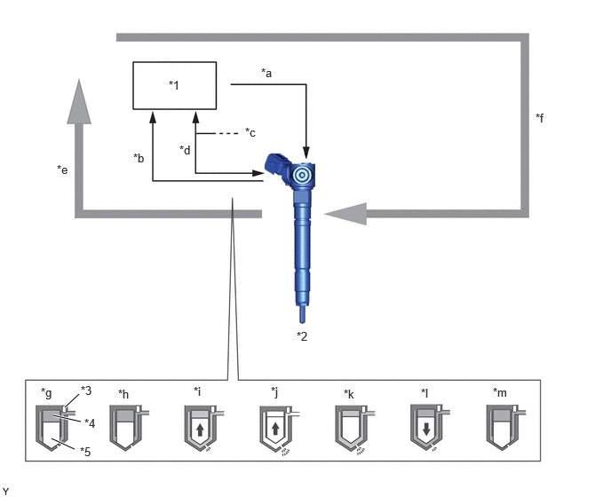
| *1 | ECM | *2 | Injector Assembly
·
Fuel Pressure Sensor
·
Fuel Temperature Sensor
·
Memory IC |
| *3 | Fuel Pressure Sensor | *4 | Control Chamber |
| *5 | Nozzle Needle | - | - |
| *a | Operating Signal | *b | Fuel Pressure Signal |
| *c | Each Injector Assembly | *d | INJ Communication (Fuel Temperature Signal and Memory IC Communication) |
| *e | Feedback | *f | Command Signal |
| *g | When there is no injection | *h | When electrical current starts to flow |
| *i | When injection starts | *j | When the maximum injection rate has been reached |
| *k | When electrical current flow has stopped | *l | When the injection rate has been reduced |
| *m | When injection has stopped | - | - |

|
Nozzle Needle Movement | - | - |