Home › Engine / Hybrid System › F33A-FTV (INTAKE / EXHAUST) › INTAKE SYSTEM › from 2021.07
NM38G0E _51 Engine / Hybrid System _106498 F33A-FTV INTAKE / EXHAUST _0489395 INTAKE SYSTEM DE DETAILS F

F33A-FTV INTAKE / EXHAUST  INTAKE SYSTEM  DETAILS  TURBOCHARGER  


CONSTRUCTION


a.

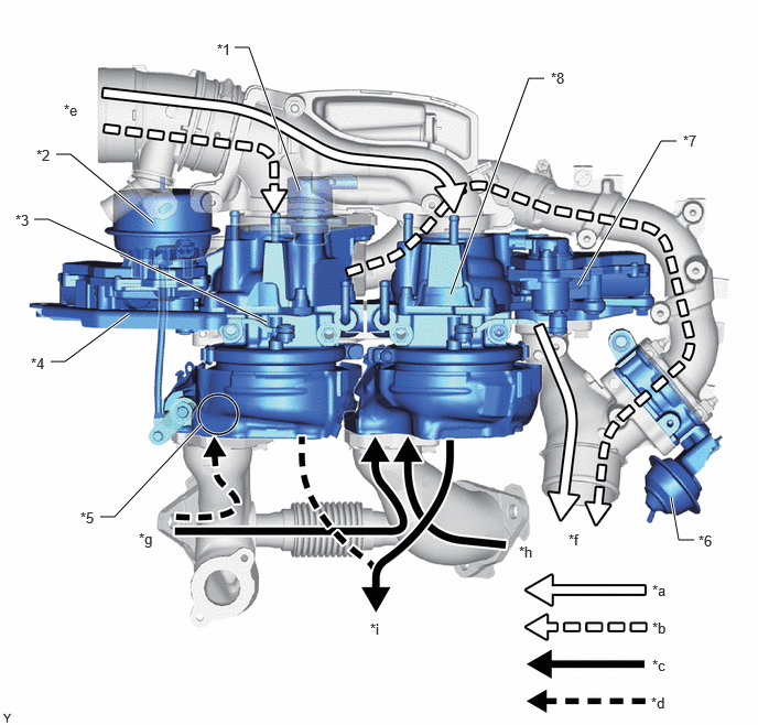
A variable nozzle vane type of 2 way twin turbocharger is used to achieve turbocharging characteristics capable of delivering a comfortable feeling of acceleration in various driving situations. In the low-speed range, single turbo mode contributes toward providing powerful acceleration with highly responsive turbocharging characteristics. In the high-speed range, twin turbo mode contributes toward providing smooth acceleration with high turbocharging characteristics with a high intake air volume.
W149182C01
2.219,0.448 2.354,0.448 2.354,0.448 2.833,1.802 true 0.531,1.458 0.667,1.458 0.667,1.458 1.448,2.104 true 0.323,2.073 0.458,2.073 0.458,2.073 2.521,3.042 true 6.396,1.333 6.25,1.333 6.25,1.333 5.469,2.698 true 6.563,5.104 6.417,5.104 6.417,5.104 6.344,4.698 true 0.479,3.417 0.615,3.417 0.615,3.417 1.219,2.969 true 5.146,0.74 5,0.74 5,0.74 4.26,2.781 true 0.948,4.885 1.083,4.885 1.083,4.885 1.906,4.01 true 2.052,0.385 2.365,0.542 0.313,0.156 10 false *1 0.344,1.385 0.656,1.542 0.313,0.156 10 false *2 0.146,2 0.458,2.156 0.313,0.156 10 false *3 0.76,4.813 1.073,4.969 0.313,0.156 10 false *5 6.604,5.031 6.917,5.188 0.313,0.156 10 false *6 6.167,5.5 6.479,5.656 0.313,0.156 10 false *a 6.458,1.25 6.771,1.406 0.313,0.156 10 false *7 5.208,0.656 5.521,0.813 0.313,0.156 10 false *8 6.167,5.854 6.479,6.01 0.313,0.156 10 false *b 0.292,3.354 0.604,3.51 0.313,0.156 10 false *4 6.167,6.208 6.479,6.365 0.313,0.156 10 false *c 6.156,6.563 6.469,6.719 0.313,0.156 10 false *d 5.375,5.021 5.688,5.177 0.313,0.156 10 false *f 3.5,5.865 3.813,6.021 0.313,0.156 10 false *i 0.604,0.958 0.917,1.115 0.313,0.156 10 false *e 1.313,5.01 1.625,5.167 0.313,0.156 10 false *g 4.906,5.135 5.219,5.292 0.313,0.156 10 false *h
*1 Air By-pass Valve Assembly *2 Actuator with Bracket Assembly
*3 No. 2 Turbocharger Sub-assembly *4 No. 2 Turbocharger Variable Nozzle Motor
*5 Exhaust Control Valve *6 Intake Air Control Valve Assembly
*7 Turbocharger Variable Nozzle Motor *8 Turbocharger Sub-assembly
*a Intake Air Flow of Single Turbo Mode and Twin Turbo Mode *b Intake Air Flow of Twin Turbo Mode
*c Exhaust Gas Flow of Single Turbo Mode and Twin Turbo Mode *d Exhaust Gas Flow of Twin Turbo Mode
*e From Air Cleaner Assembly *f To Intercooler Assembly
*g From Cylinder Head LH *h From Cylinder Head Sub-assembly
*i To Exhaust Pipe - -


b.

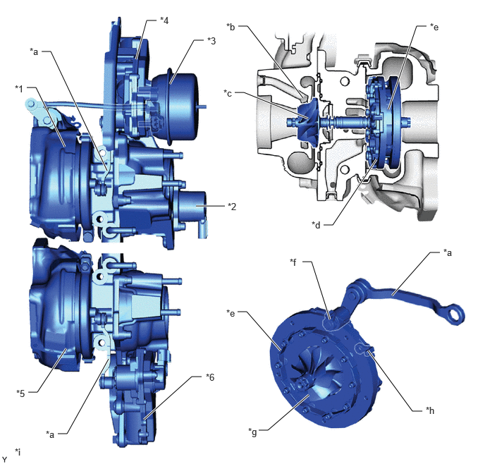
A water jacket is added to the compressor housing to cool intake air passage walls and suppress the accumulation of deposits, allowing turbo pressure to be increased further and contributing toward increasing engine output.


c.

The shapes of the compressor wheel and compressor housing are optimized to improve turbocharging efficiency, contributing toward improving engine output, improving low speed torque and improving fuel efficiency.


d.

Variable nozzle vanes are used to contribute significantly toward improving low speed torque, maximum output, and fuel efficiency, and toward decreasing exhaust gas. This is achieved by controlling the position of variable nozzle vanes and having the optimal amount of exhaust gas flow into the turbine wheel, based on engine conditions.


e.

The variable nozzle vane type turbocharger sub-assembly consists primarily of a compressor wheel, turbine wheel, nozzle vane, unison ring, drive arm, driven arm, turbocharger variable nozzle motor (motor and nozzle vane position sensor) and nozzle vane control link.


f.

The ECM outputs a signal to the turbocharger sub-assembly, which operates the turbocharger variable nozzle motor to control the nozzle vane position.
W149183C01
0.396,1.292 0.531,1.292 0.531,1.292 0.958,2.167 true 2.313,0.302 2.167,0.302 2.167,0.302 2.01,0.875 true 0.615,0.76 0.75,0.76 0.75,0.76 1.583,2.521 true 3.01,0.594 2.865,0.594 2.865,0.594 2.51,1.24 true 2.896,3.042 3.323,3.042 true 2.979,5.563 2.833,5.563 2.833,5.563 2.125,6.198 true 0.854,6.406 0.99,6.406 0.99,6.406 1.604,5.302 true 0.417,5.792 0.552,5.792 0.552,5.792 0.979,5.146 true 3.469,1.365 3.604,1.365 3.604,1.365 4.552,1.75 true 4.781,3.323 4.917,3.323 4.917,3.323 5.563,2.354 true 6.302,0.385 6.156,0.385 6.156,0.385 5.74,1.615 true 6.5,3.729 6.354,3.729 6.354,3.729 5.792,4.365 true 4.469,3.865 4.604,3.865 4.604,3.865 4.875,4.719 true 3.51,4.604 3.646,4.604 3.646,4.604 4.146,5.177 true 3.823,6.354 3.958,6.354 3.958,6.354 4.563,5.833 true 6.24,6.073 6.094,6.073 6.094,6.073 5.438,5.177 true 3.521,0.385 3.656,0.385 3.656,0.385 4.479,1.448 true 0.219,1.229 0.531,1.385 0.313,0.156 10 false *1 3.365,2.969 3.677,3.125 0.313,0.156 10 false *2 3.063,0.521 3.375,0.677 0.313,0.156 10 false *3 2.365,0.219 2.677,0.375 0.313,0.156 10 false *4 0.24,5.729 0.552,5.885 0.313,0.156 10 false *5 3.042,5.49 3.354,5.646 0.313,0.156 10 false *6 0.438,0.677 0.75,0.833 0.313,0.156 10 false *a 3.302,1.292 3.615,1.448 0.313,0.156 10 false *c 4.604,3.24 4.917,3.396 0.313,0.156 10 false *d 6.354,0.313 6.667,0.469 0.313,0.156 10 false *e 4.281,3.792 4.594,3.948 0.313,0.156 10 false *f 3.667,6.292 3.979,6.448 0.313,0.156 10 false *g 6.292,5.979 6.604,6.135 0.313,0.156 10 false *h 0.219,6.594 0.531,6.75 0.313,0.156 10 false *i 0.677,6.333 0.99,6.49 0.313,0.156 10 false *a 3.344,4.542 3.656,4.698 0.313,0.156 10 false *e 6.552,3.646 6.865,3.802 0.313,0.156 10 false *a 3.344,0.313 3.656,0.469 0.313,0.156 10 false *b
*1 No. 2 Turbocharger Sub-assembly *2 Air By-pass Valve Assembly
*3 Actuator with Bracket Assembly *4 No. 2 Turbocharger Variable Nozzle Motor
*5 Turbocharger Sub-assembly *6 Turbocharger Variable Nozzle Motor
*a Linkage *b Water Jacket
*c Compressor Wheel *d Unison Ring
*e Nozzle Vane *f Drive Arm
*g Turbine Wheel *h Driven Arm
*i The illustration is a representative example. - -


OPERATION


a.

Nozzle Vane Control

i.

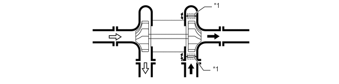
Exhaust gas from the cylinder head passes through the variable nozzle vanes in the turbocharger housing and flows into the exhaust pipe through the turbine wheel. The speed (turbo pressure) of the turbine wheel varies depending on the speed of the exhaust gas passing through the turbine wheel, and the speed of the exhaust gas is controlled by the variable nozzle vanes. When there is little exhaust gas (such as while idling), the nozzle vanes are almost completely shut. However, some exhaust gas flows into the exhaust pipe through the small gaps around each nozzle vane.
W123704C01
4.104,0.302 4.323,0.146 4.323,0.146 4.479,0.146 true 4.094,1.208 4.302,1.5 4.302,1.5 4.448,1.5 true 4.521,0.031 4.833,0.229 0.313,0.198 10 false *1 4.5,1.385 4.813,1.583 0.313,0.198 10 false *1
*1 Nozzle Vane - -
V100136

Intake Air
V100135

Exhaust Gas


b.

At Low Load Range or Low Speed Range

i.

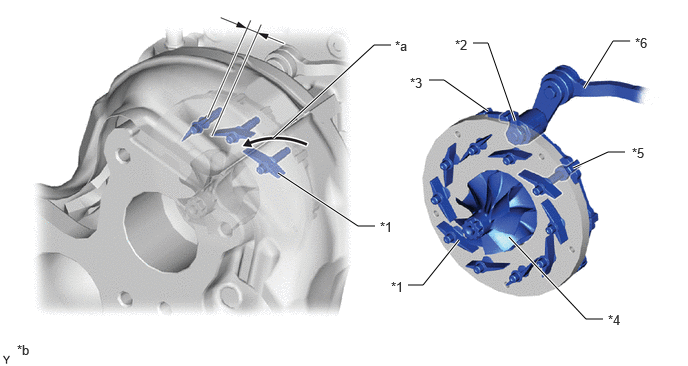
The turbocharger variable nozzle motor moves the linkage in the closing direction of the nozzle vanes in accordance with signals from the ECM.


ii.

This causes an increase in the speed at which the exhaust gas flows into the turbine wheel, causing the speed of the turbine wheel to increase. As a result, the low speed torque of the engine is improved.
W149184C01
2.844,1.438 3.896,0.469 3.896,0.469 4.073,0.469 true 5.365,1.26 5.083,0.448 5.083,0.448 4.927,0.448 true 2.896,1.802 3.729,2.354 3.729,2.354 3.906,2.354 true 5.083,1.156 4.625,0.833 4.625,0.833 4.469,0.833 true 5.302,2.469 6.104,3.323 6.104,3.323 6.281,3.323 true 4.781,2.5 4.406,2.969 4.406,2.969 4.25,2.969 true 5.969,1.75 6.333,1.583 6.333,1.583 6.51,1.583 true 6.083,0.917 6.385,0.427 6.385,0.427 6.563,0.427 true 3.958,2.281 4.271,2.438 0.313,0.156 10 false *1 4.74,0.385 5.052,0.542 0.313,0.156 10 false *2 4.271,0.781 4.583,0.948 0.313,0.167 10 false *3 6.333,3.25 6.646,3.427 0.313,0.177 10 false *4 6.583,1.51 6.896,1.719 0.313,0.208 10 false *5 6.615,0.365 6.927,0.563 0.313,0.198 10 false *6 4.115,0.396 4.469,0.573 0.354,0.177 10 false *a 0.177,3.563 0.531,3.74 0.354,0.177 10 false *b 4.073,2.906 4.385,3.063 0.313,0.156 10 false *1
*1 Nozzle Vane *2 Driven Arm
*3 Unison Ring *4 Turbine Wheel
*5 Driven Arm *6 Linkage
*a Exhaust Gas Flow *b The illustration is a representative example.


c.

At High Load Range or Medium-to-high Speed Range

i.

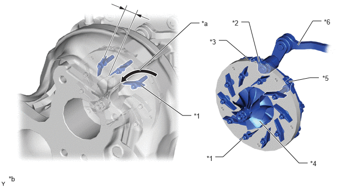
The turbocharger variable nozzle motor moves the linkage in the opening direction of the nozzle vanes in accordance with signals from the ECM. This opens the nozzle vane and holds the specified supercharging pressure, lowering the back pressure and improving the output and fuel consumption.
W149185C01
2.844,1.438 3.896,0.469 3.896,0.469 4.073,0.469 true 5.292,1.26 5.083,0.448 5.083,0.448 4.927,0.448 true 2.875,1.74 3.729,2.354 3.729,2.354 3.906,2.354 true 5.042,1.177 4.625,0.823 4.625,0.823 4.469,0.823 true 5.302,2.469 6.104,3.323 6.104,3.323 6.281,3.323 true 4.958,2.823 4.552,3.198 4.552,3.198 4.396,3.198 true 5.896,1.667 6.333,1.583 6.333,1.583 6.51,1.583 true 6.083,0.917 6.385,0.427 6.385,0.427 6.563,0.427 true 3.958,2.281 4.271,2.438 0.313,0.156 10 false *1 4.74,0.385 5.052,0.542 0.313,0.156 10 false *2 4.281,0.771 4.594,0.938 0.313,0.167 10 false *3 6.333,3.25 6.646,3.427 0.313,0.177 10 false *4 6.583,1.51 6.896,1.719 0.313,0.208 10 false *5 6.615,0.365 6.927,0.563 0.313,0.198 10 false *6 4.115,0.396 4.469,0.573 0.354,0.177 10 false *a 0.177,3.563 0.531,3.74 0.354,0.177 10 false *b 4.219,3.146 4.531,3.302 0.313,0.156 10 false *1
*1 Nozzle Vane *2 Driven Arm
*3 Unison Ring *4 Turbine Wheel
*5 Driven Arm *6 Linkage
*a Exhaust Gas Flow *b The illustration is a representative example.


d.

2 Way Twin Turbo Control

i.

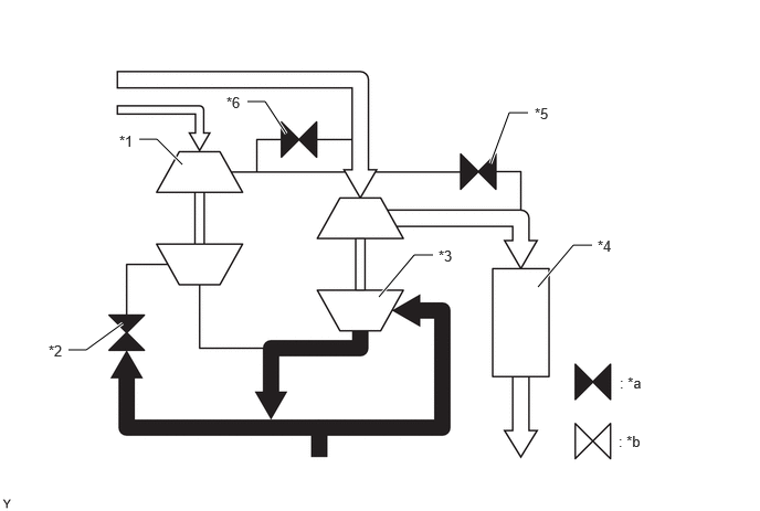
Turbo mode switching is performed by combining the opening or closing of the intake air control valve assembly, air by-pass valve assembly and exhaust control valve.


ii.

Single Turbo Mode

1.

The supply of exhaust gas to the No. 2 turbocharger sub-assembly is shut off and the intake air to the No. 2 turbocharger sub-assembly is shut off by closing the intake air control valve assembly, exhaust control valve and air by-pass valve assembly.
W149196C01
1.313,1.313 1.479,1.313 1.479,1.313 1.719,1.552 true 4.625,1.542 4.802,1.063 4.802,1.063 4.979,1.063 true 0.646,3.302 0.813,3.302 0.813,3.302 1.156,3.052 true 3.573,2.802 3.906,2.406 3.906,2.406 4.083,2.406 true 5.073,2.708 5.406,2.313 5.406,2.313 5.583,2.313 true 2.333,0.958 2.5,0.958 2.5,0.958 2.698,1.26 true 1.125,1.25 1.438,1.406 0.313,0.156 10 false *1 0.458,3.229 0.771,3.385 0.313,0.156 10 false *2 4.135,2.333 4.448,2.49 0.313,0.156 10 false *3 5.635,2.24 5.948,2.396 0.313,0.156 10 false *4 5.042,0.99 5.354,1.146 0.313,0.156 10 false *5 2.135,0.885 2.448,1.042 0.313,0.156 10 false *6 5.844,3.531 6.156,3.688 0.313,0.156 10 false : *a 5.833,4.083 6.146,4.24 0.313,0.156 10 false : *b
*1 No. 2 Turbocharger Sub-assembly *2 Exhaust Control Valve
*3 Turbocharger Sub-assembly *4 Intercooler Assembly
*5 Intake Air Control Valve Assembly *6 Air By-pass Valve Assembly
*a Valve Close *b Valve Open
V100135

Exhaust Gas Flow
V100136

Intake Air Flow


iii.

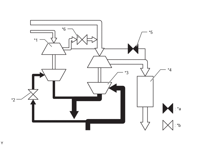
When Switching Turbo Mode

1.

The transition to twin turbo mode is performed smoothly by opening the exhaust control valve and operating the No. 2 turbocharger sub-assembly in advance. Also, the mode can also be quickly switched to twin mode by opening the bypass valve assembly, returning intake air to the upstream side of the turbocharger sub-assembly and rapidly increasing the speed of the turbine wheel.
W149197C01
1.313,1.313 1.479,1.313 1.479,1.313 1.719,1.552 true 4.531,1.542 4.708,1.063 4.708,1.063 4.885,1.063 true 0.542,3.302 0.708,3.302 0.708,3.302 1.052,3.052 true 3.573,2.802 3.906,2.406 3.906,2.406 4.083,2.406 true 4.99,2.708 5.323,2.313 5.323,2.313 5.5,2.313 true 2.24,0.958 2.406,0.958 2.406,0.958 2.604,1.26 true 1.125,1.25 1.438,1.406 0.313,0.156 10 false *1 0.375,3.24 0.688,3.396 0.313,0.156 10 false *2 4.135,2.333 4.448,2.49 0.313,0.156 10 false *3 5.563,2.24 5.875,2.396 0.313,0.156 10 false *4 4.938,0.99 5.25,1.146 0.313,0.156 10 false *5 2.052,0.885 2.365,1.042 0.313,0.156 10 false *6 5.802,3.531 6.115,3.688 0.313,0.156 10 false : *a 5.792,4.083 6.104,4.24 0.313,0.156 10 false : *b
*1 No. 2 Turbocharger Sub-assembly *2 Exhaust Control Valve
*3 Turbocharger Sub-assembly *4 Intercooler Assembly
*5 Intake Air Control Valve Assembly *6 Air By-pass Valve Assembly
*a Valve Close *b Valve Open
V100135

Exhaust Gas Flow
V100136

Intake Air Flow


iv.

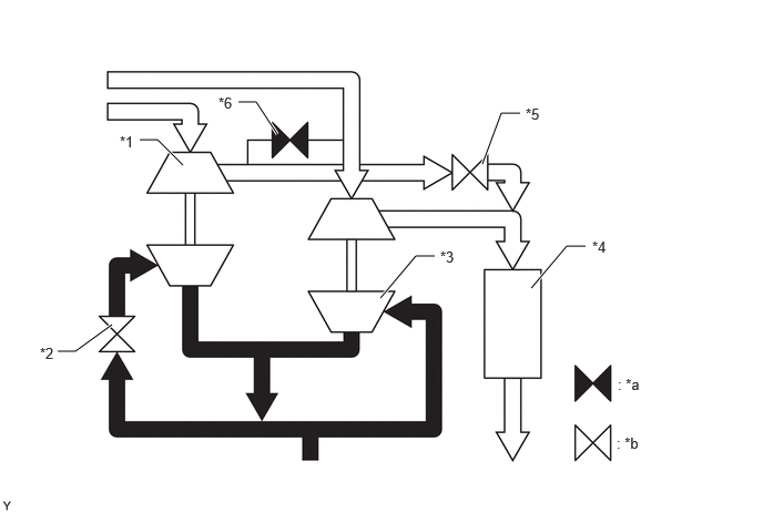
Twin Turbo Mode

1.

The exhaust control valve and intake air control valve assembly are opened to supply the intake air from the No. 2 turbocharger sub-assembly to the engine.
W149198C01
1.313,1.313 1.479,1.313 1.479,1.313 1.719,1.552 true 4.531,1.542 4.708,1.063 4.708,1.063 4.885,1.063 true 0.542,3.302 0.708,3.302 0.708,3.302 1.052,3.052 true 3.573,2.802 3.906,2.406 3.906,2.406 4.083,2.406 true 4.99,2.708 5.323,2.313 5.323,2.313 5.5,2.313 true 2.24,0.958 2.406,0.958 2.406,0.958 2.604,1.26 true 1.125,1.25 1.438,1.406 0.313,0.156 10 false *1 0.375,3.24 0.688,3.396 0.313,0.156 10 false *2 4.135,2.333 4.448,2.49 0.313,0.156 10 false *3 5.563,2.24 5.875,2.396 0.313,0.156 10 false *4 4.938,0.99 5.25,1.146 0.313,0.156 10 false *5 2.052,0.885 2.365,1.042 0.313,0.156 10 false *6 5.802,3.531 6.115,3.688 0.313,0.156 10 false : *a 5.792,4.083 6.104,4.24 0.313,0.156 10 false : *b
*1 No. 2 Turbocharger Sub-assembly *2 Exhaust Control Valve
*3 Turbocharger Sub-assembly *4 Intercooler Assembly
*5 Intake Air Control Valve Assembly *6 Air By-pass Valve Assembly
*a Valve Close *b Valve Open
V100135

Exhaust Gas Flow
V100136

Intake Air Flow