SUSPENSION CONTROL ELECTRONIC-KINETIC DYNAMIC SUSPENSION SYSTEM CONTROL ELECTRONIC-KINETIC DYNAMIC SUSPENSION CONTROL
FUNCTION OF MAIN COMPONENTS
| Component | Function | |
|---|---|---|
|
*: GR SPORT |
||
| Stabilizer Bar | Suppresses rolling while driving. | |
| Front Stabilizer Control Cylinder | Expands or contracts linked to the movement of the stabilizer bar to control the stabilizer bar function. | |
| Front Stabilizer Control Cylinder LH | Expands or contracts linked to the movement of the stabilizer bar to control the stabilizer bar function. | |
| Rear Stabilizer Control Cylinder | Expands or contracts linked to the movement of the stabilizer bar to control the stabilizer bar function. | |
| Stabilizer Control Valve Sub-assembly | Accumulator Cut Valve |
·
Sends changes to the oil volume caused by temperature changes on the front cylinder side to the accumulator side.
·
Closes when the pressure on the front cylinder side rises when turning while the stabilizer is locked. |
| Oil Supply Valve | Used when filling oil. | |
| Bleeder Plug | Used for air bleeding when filling oil. | |
| Front Stabilizer Housing Sub-assembly | Front Normal Open Solenoid Valve | Opens and closes according to the signals from the stabilizer control ECU to switch the oil passages on the front cylinder side. |
| Front Normal Closed Solenoid Valve | Opens and closes according to the signals from the stabilizer control ECU to switch the oil passages on the front cylinder side. | |
| Stabilizer Control Housing with Accumulator Assembly | Rear Lower Chamber Solenoid Valve | Opens and closes according to the signals from the stabilizer control ECU to switch the oil passages on the rear cylinder side. |
| Rear Upper Chamber Solenoid Valve | Opens and closes according to the signals from the stabilizer control ECU to switch the oil passages on the rear cylinder side. | |
| Accumulator |
·
Absorbs changes to the oil volume caused by temperature changes on the front cylinder side and rear cylinder side.
·
Absorbs changes to the oil volume caused by entry of the rod of the rear cylinder. |
|
| Combination Meter Assembly | Multi-information Display | Displays a message when a system malfunction occurs. |
| Airbag ECU (Airbag ECU Assembly) | Yawrate Sensor (deceleration signal) | Detects the vehicle's lateral deceleration. |
| Steering Sensor | Detects the steering direction, steering angle and steering angle velocity of the steering wheel. | |
| Stabilizer Control ECU | Controls the solenoid valves based on the signals from the sensors and ECUs. | |
| Brake Actuator Assembly | No. 2 Skid Control ECU | Sends vehicle speed signals, vehicle left/right acceleration signals and multi-terrain select AUTO mode judgment signals to the stabilizer control ECU. |
| ECM |
·
Sends the mode select signal of multi-terrain select to the stabilizer control ECU.
·
Sends the mode select signal of drive mode select to the stabilizer control ECU.* |
|
| 4 Wheel Drive Control ECU | Sends the L4 position condition signals to the stabilizer control ECU. | |
SYSTEM CONTROL
The stabilizer control ECU controls the 4 stabilizer control solenoid valves to switch the stabilizer between locked and free based on the signals from the sensors and ECUs.
Stabilizer Switching Control
The stabilizer control ECU determines the road surface conditions based on the signals of the wheel speed sensors, and determines whether the stabilizers are locked or free based on the information for the vehicle speed, left/right acceleration (lateral G) and steering speed.
Determination of Road Surface Conditions
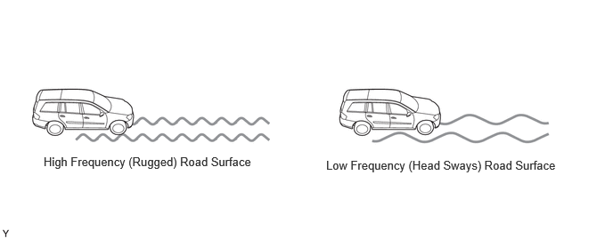
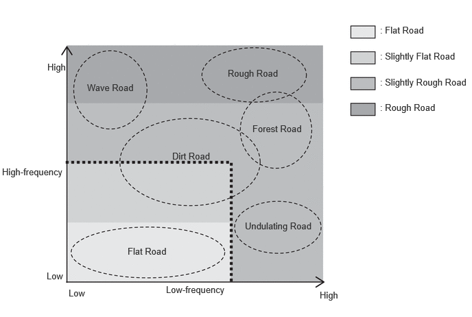
The stabilizer control ECU determines the road surface conditions and divides the conditions into 4 categories based on the following 2 wheel speed sensor signals sent from the No. 2 skid control ECU.
Determines high frequency (rugged) road surfaces from the acceleration of the wheel speed sensor signals
Determines low frequency (head sways) road surfaces from the difference between the left and right wheel speeds of the wheel speed sensor signals
Locked or Free Determination
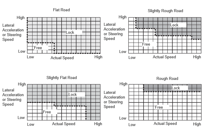
Based on the 4 road surface conditions that were determined, the stabilizer control ECU determines whether the stabilizers are locked or free according to the lateral acceleration of the vehicle, steering speed and actual vehicle speed. On good roads with a road surface in a good condition, the lock timing of the stabilizers is advanced to ensure superior driving stability.
L4 Drive Mode Control
The stabilizer control ECU detects off-road driving from the signals of the drive mode (L4) sent from the 4 wheel drive control ECU, and expands the range in which the stabilizers are free. This ensures superior off-road driving performance.
Multi-terrain Select Switching Control
The stabilizer control ECU switches the stabilizers according to the selected mode based on the mode select signal of multi-terrain select sent from the ECM. During AUTO mode, the stabilizers are switched according to judgment signals sent from the No. 2 skid control ECU.
| Transfer Drive Mode | Multi-terrain Select Mode | Vehicle Status | E-KDSS Control |
|---|---|---|---|
| H4 | AUTO | Straight ahead | Both the front and rear sides are set to free for excellent ride comfort. |
| Turning | The front and rear sides are optimally set to locked or free based on multi-terrain select AUTO mode judgment results. | ||
| DIRT, MUD, DEEP SNOW | Straight ahead | Both the front and rear sides are set to free for excellent ride comfort. | |
| Turning | The front side is set to locked and the rear side is set to free to ensure driving stability. | ||
| SAND | Straight ahead | Both the front and rear sides are set to free for excellent ride comfort. | |
| Turning | Both the front and rear sides are set to locked to ensure turning performance. | ||
| L4 | AUTO, ROCK, MUD, SAND | - | The free range is expanded for both the front and rear sides to improve off-road driving performance. |
Drive Mode Select Switching Control (GR SPORT)
Switches stabilizer control characteristics according to the drive mode selected by drive mode select operations.
| Drive Mode | E-KDSS Control | Outline |
|---|---|---|
| NOMAL, ECO, COMFORT, SPORT S | NOMAL | Achieves a good balance of high-level steering response, flat feeling, sense of stability and riding comfort. |
| SPORT S+ | SPORT | Achieves a sporty driving feel with an emphasis on superior driving stability by advancing the timing of lock switching by the stabilizer. |
FAIL-SAFE
The fail-safe function operates when a system malfunction occurs. At this time, a message is displayed on the multi-information display in the combination meter assembly to inform the driver of a system malfunction.
DIAGNOSIS
A diagnostic function has been provided to simplify system inspections. For diagnosis troubleshooting procedures and items, refer to the Repair Manual.