NM38G0E _51 Engine / Hybrid System _106497 F33A-FTV EMISSION CONTROL _0489400 EXHAUST GAS RECIRCULATION SYSTEM DE DETAILS F
F33A-FTV EMISSION CONTROL EXHAUST GAS RECIRCULATION SYSTEM DETAILS EGR PIPE AND EGR VALVE
CONSTRUCTION
a.
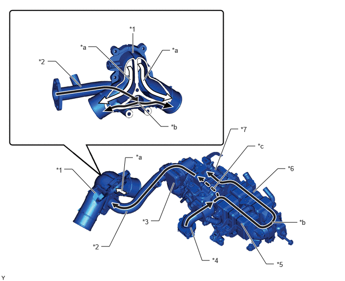
A distribution mechanism for the EGR gas and intake air is used in the No. 1 intake pipe and No. 4 EGR pipe. The EGR gas and intake air are distributed evenly to the 6 cylinders on the left and right to reduce emissions and improve fuel efficiency.
1.333,3.51 1.5,3.51 1.5,3.51 1.979,4.01 true 2.979,1.677 3.375,1.042 3.375,1.042 3.531,1.042 true 2.865,2.125 3.344,2.625 3.344,2.625 3.5,2.625 true 1.833,0.969 2,0.969 2,0.969 2.708,1.656 true 2.76,1.104 2.76,0.688 true 2.531,3.969 2.604,3.271 2.604,3.271 2.76,3.271 true 3.135,4.583 3.302,4.583 3.302,4.583 3.615,3.792 true 2.104,5.115 2.271,5.115 2.271,5.115 2.635,4.385 true 0.99,1.271 1.156,1.271 1.156,1.271 1.688,1.802 true 3.958,4.719 4.198,5.406 4.198,5.406 4.354,5.406 true 5.01,4.635 5.531,5.479 5.531,5.479 5.688,5.479 true 4.469,3.531 4.792,2.677 4.792,2.677 4.948,2.677 true 5.646,4.615 6.177,4.615 true 4.427,3.927 5.146,3.031 5.146,3.031 5.302,3.031 true 5.26,3.99 5.771,3.5 5.771,3.5 5.927,3.5 true 2.688,0.521 3,0.677 0.313,0.156 10 false *1 1.927,5.042 2.24,5.198 0.313,0.156 10 false *2 2.958,4.521 3.271,4.677 0.313,0.156 10 false *3 4.406,5.323 4.719,5.479 0.313,0.156 10 false *4 5.75,5.406 6.063,5.563 0.313,0.156 10 false *5 5.979,3.417 6.292,3.573 0.313,0.156 10 false *6 5,2.604 5.313,2.76 0.313,0.156 10 false *7 1.667,0.896 1.979,1.052 0.313,0.156 10 false *a 6.219,4.531 6.531,4.688 0.313,0.156 10 false *b 5.354,2.948 5.667,3.104 0.313,0.156 10 false *c 1.167,3.448 1.479,3.604 0.313,0.156 10 false *1 0.802,1.198 1.115,1.354 0.313,0.156 10 false *2 3.573,0.958 3.885,1.115 0.313,0.156 10 false *a 3.552,2.552 3.865,2.708 0.313,0.156 10 false *b 2.823,3.177 3.135,3.333 0.313,0.156 10 false *a
| *1 | No. 1 Intake Pipe | *2 | No. 4 EGR Pipe |
| *3 | Electric EGR Control Valve Assembly | *4 | EGR Inlet |
| *5 | No. 1 EGR Cooler | *6 | No. 2 EGR Cooler |
| *7 | No. 2 EGR Valve Assembly | - | - |
| *a | Intake Air | *b | EGR Gas |
| *c | EGR Gas (through Bypass Passage) | - | - |
b.
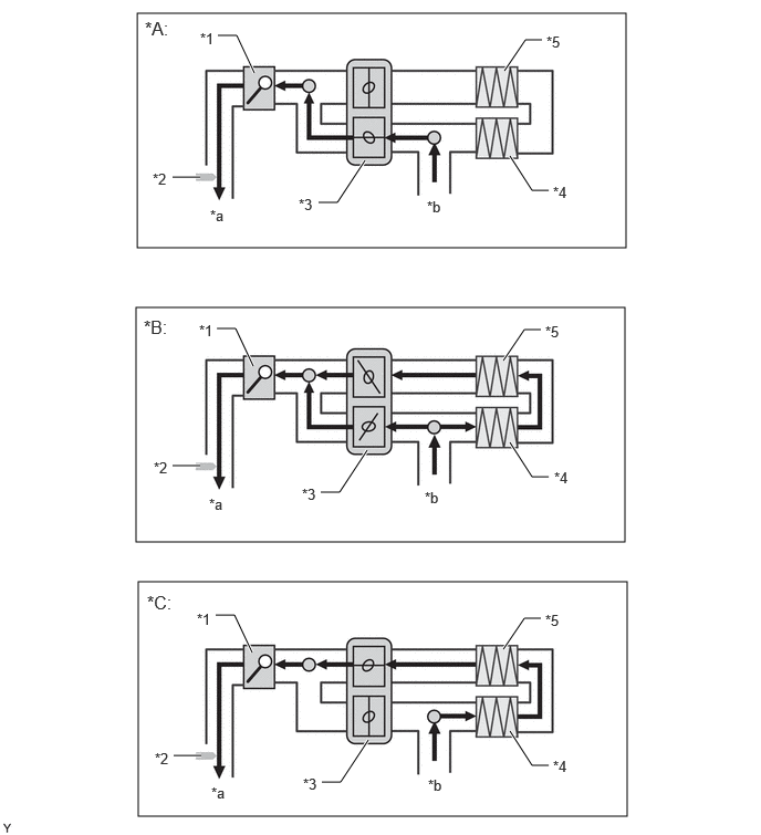
A No. 2 EGR valve assembly is used to optimize the EGR gas temperature. The No. 2 EGR valve assembly uses a DC motor to change the angle of the bypass valve continuously, controlling the amount of EGR gas passing through the No. 1 EGR cooler and No. 2 EGR cooler.
1.292,0.125 5.896,2.333 4.604,2.208 1.281,2.896 5.885,5.104 4.604,2.208 1.302,5.479 5.906,7.688 4.604,2.208 4.802,1.469 5.01,1.792 5.01,1.792 5.167,1.792 true 2.052,0.333 2.229,0.333 2.229,0.333 2.396,0.688 true 1.625,1.667 1.885,1.667 true 3,1.906 3.177,1.906 3.177,1.906 3.438,1.51 true 4.75,0.667 4.948,0.375 4.948,0.375 5.104,0.375 true 2.042,3.094 2.219,3.094 2.219,3.094 2.385,3.448 true 1.625,4.385 1.885,4.385 true 4.74,3.396 4.938,3.104 4.938,3.104 5.094,3.104 true 4.802,4.167 5.01,4.49 5.01,4.49 5.167,4.49 true 3.021,4.635 3.198,4.635 3.198,4.635 3.458,4.24 true 2.031,5.792 2.208,5.792 2.208,5.792 2.375,6.146 true 1.635,7.115 1.896,7.115 true 3.031,7.365 3.208,7.365 3.208,7.365 3.469,6.969 true 4.802,6.885 5.01,7.208 5.01,7.208 5.167,7.208 true 4.74,6.115 4.938,5.823 4.938,5.823 5.094,5.823 true 1.365,0.167 1.708,0.385 0.344,0.219 12 false *A: 1.354,2.979 1.75,3.198 0.396,0.219 12 false *B: 1.385,5.573 1.76,5.813 0.375,0.24 12 false *C: 1.885,0.281 2.198,0.438 0.313,0.156 10 false *1 1.438,1.604 1.75,1.76 0.313,0.156 10 false *2 2.813,1.844 3.125,2 0.313,0.156 10 false *3 5.208,1.729 5.521,1.885 0.313,0.156 10 false *4 5.135,3.042 5.448,3.198 0.313,0.156 10 false *5 1.979,1.948 2.292,2.104 0.313,0.156 10 false *a 4.021,1.865 4.333,2.021 0.313,0.156 10 false *b 1.875,3.031 2.188,3.188 0.313,0.156 10 false *1 1.448,4.323 1.76,4.479 0.313,0.156 10 false *2 5.146,0.313 5.458,0.469 0.313,0.156 10 false *5 5.219,4.417 5.531,4.573 0.313,0.156 10 false *4 4,4.604 4.313,4.76 0.313,0.156 10 false *b 1.969,4.667 2.281,4.823 0.313,0.156 10 false *a 2.844,4.573 3.156,4.729 0.313,0.156 10 false *3 1.854,5.75 2.167,5.906 0.313,0.156 10 false *1 1.458,7.063 1.771,7.219 0.313,0.156 10 false *2 1.99,7.385 2.302,7.542 0.313,0.156 10 false *a 2.854,7.302 3.167,7.458 0.313,0.156 10 false *3 4.031,7.313 4.344,7.469 0.313,0.156 10 false *b 5.208,7.135 5.521,7.292 0.313,0.156 10 false *4 5.135,5.76 5.448,5.917 0.313,0.156 10 false *5
| *A | Bypass Mode | *B | Cooler and Bypass Mode |
| *C | Cooler Bypass Mode | - | - |
| *1 | Electric EGR Control Valve Assembly | *2 | EGR Gas Temperature Sensor |
| *3 | No. 2 EGR Valve Assembly | *4 | No. 1 EGR Cooler |
| *5 | No. 2 EGR Cooler | - | - |
| *a | To No. 1 Intake Pipe | *b | From Cylinder Head |

|
EGR Gas Flow | - | - |