NM38G0E _51 Engine / Hybrid System _106497 F33A-FTV EMISSION CONTROL _0489400 EXHAUST GAS RECIRCULATION SYSTEM DE DETAILS F
F33A-FTV EMISSION CONTROL EXHAUST GAS RECIRCULATION SYSTEM DETAILS EGR COOLER
CONSTRUCTION
a.
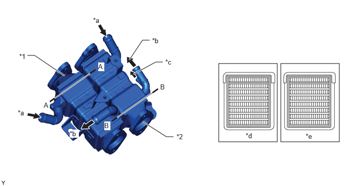
A U-flow layout is used for the water-cooled type No. 1 EGR cooler and No. 2 EGR cooler to make the coolant flow of the No. 2 EGR cooler in opposite directions, cooling the EGR gas efficiently and saving space.
b.
The EGR gas is cooled by the coolant as it passes through 8-layered gas passages within the No. 1 EGR cooler and No. 2 EGR cooler.
5.75,1.302 6.948,2.906 1.198,1.604 4.479,1.302 5.677,2.906 1.198,1.604 0.563,1.135 0.708,1.135 0.708,1.135 1.323,1.552 true 2.917,2.49 3.406,2.802 3.406,2.802 3.552,2.802 true 2.729,1.521 3.188,1.271 3.188,1.271 3.333,1.271 true 2.646,1.229 2.917,0.823 2.917,0.823 3.063,0.823 true 0.396,1.073 0.708,1.229 0.313,0.156 10 false *1 3.615,2.719 3.927,2.875 0.313,0.156 10 false *2 0.365,2.229 0.677,2.385 0.313,0.156 10 false *a 3.385,1.188 3.698,1.344 0.313,0.156 10 false *c 3.115,0.75 3.427,0.906 0.313,0.156 10 false *b 1.906,0.333 2.219,0.49 0.313,0.156 10 false *a 5.031,2.698 5.344,2.854 0.313,0.156 10 false *d 6.26,2.708 6.573,2.865 0.313,0.156 10 false *e 1.427,2.656 1.615,2.823 0.188,0.167 10 true *b 0.896,2.073 1.021,2.25 0.125,0.177 10 true A 2.01,1.281 2.135,1.458 0.125,0.177 10 true A 2.135,2.49 2.26,2.667 0.125,0.177 10 true B 3.281,1.698 3.406,1.875 0.125,0.177 10 true B
| *1 | No. 1 EGR Cooler | *2 | No. 2 EGR Cooler |
| *a | From Cylinder Head LH | *b | To Engine Water Pump Assembly |
| *c | To No.2 EGR Valve Assembly | *d | A - A Cross Section |
| *e | B - B Cross Section | - | - |

|
Coolant Flow | - | - |