F33A-FTV EMISSION CONTROL UREA SELECTIVE CATALYTIC REDUCTION SYSTEM CONTROL UREA SCR SYSTEM
FUNCTION OF MAIN COMPONENTS
| Component | Function | |
|---|---|---|
| ECM | Sends the signals from the sensors to the urea pump control ECU. | |
| Urea Pump Control ECU | Controls the UREA SCR system based on signals from each sensor and ECM. | |
| No. 4 Exhaust Gas Temperature Sensor | Detects the exhaust gas temperature. | |
| No. 1 Nitrogen Oxides Sensor | Detects the concentration of NOx in the exhaust gas. | |
| No. 2 Nitrogen Oxides Sensor | ||
| Urea Pump | Supplies the urea solution from the urea tank sub-assembly to the urea injector assembly. | |
| Urea Injector Assembly | Injects the urea solution. | |
| Front Exhaust Pipe Sub-assembly | SCR-DPF Catalyst | Produces a chemical reaction between the urea solution and NOx to break them down into nitrogen and water molecules (H2O). |
| SCR Catalyst | ||
| UREA Tank Sub-assembly | Stores the urea solution. | |
| UREA tube with heater Assembly | Prevents freezing by warming up the urea solution in the pipe. | |
| Combination Meter Assembly | Multi-information Display |
·
Displays the remaining amount of urea solution.
·
Displays a message when an abnormality occurs in the system. |
| Urea Solution Level Warning | Illuminates when the remaining amount of urea solution decreases to the threshold or less. | |
SYSTEM CONTROL
A UREA SCR system is used to purify NOx in the exhaust gas. The UREA SCR system injects urea solution into the exhaust gas to generate ammonia. The generated ammonia produces a chemical reaction with the NOx in the exhaust gas on the SCR-DPF catalyst and SCR catalyst, breaking it down into nitrogen and water, thereby purifying the exhaust gas.
The UREA SCR system is composed of a urea pump control ECU, urea tank sub-assembly, urea injector assembly, urea pump, No. 4 exhaust gas temperature sensor, No.1 nitrogen oxides sensor and No. 2 nitrogen oxides sensor.
In the UREA SCR system, the urea pump control ECU controls the urea injector assembly and urea pump based on various signals.
The amount of NOx in the exhaust gas increases as the engine load increases. This system injects urea solution according to the engine load in order to maintain the amount of NOx at a certain level or less.
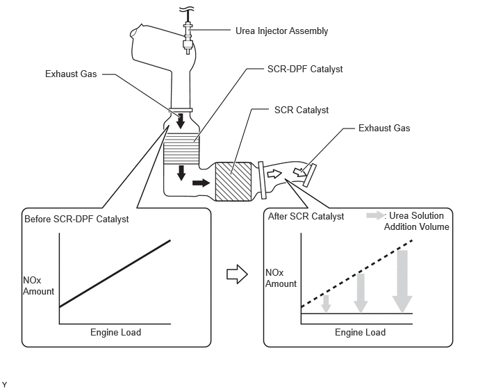
- HINT:
-
When the SCR-DPF catalyst and SCR catalyst temperature reaches a certain temperature or more, such as when high-load driving continues for a long period of time or SCR-DPF catalyst regeneration is in progress, the amount of urea solution that is injected is further increased.
The amount of urea solution that is consumed changes depending on the driving conditions and environment. During high-load driving, the amount of urea solution that is consumed increases and the driving range decreases. Inversely, during low-load driving, the amount of urea solution that is consumed decreases and the driving range increases.
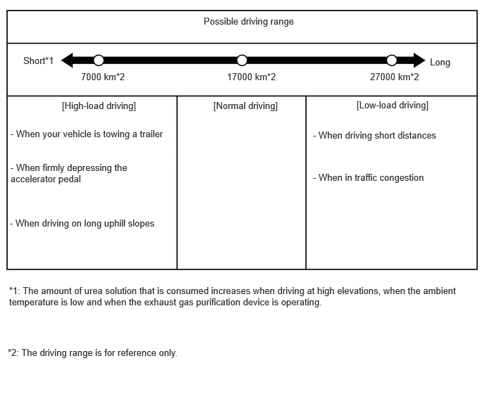
Remaining Urea Solution Display
The remaining amount of urea solution is displayed on the multi-information display, based on the urea solution level in the urea tank sub-assembly measured by the urea solution level sensor
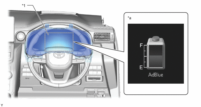
| *1 | Multi-information Display | - | - |
| *a | Remaining Urea Solution Display | - | - |