AJA0F AUTOMATIC TRANSMISSION / TRANSAXLE AUTOMATIC TRANSMISSION UNIT INSPECTION
PROCEDURE

 35781C 1.INSPECT TRANSMISSION DRIVE CHAIN
Check the transmission drive chain for wear or damage.
If any defect is found, replace the transmission drive chain.
35782 2.INSPECT DRIVE SPROCKET
Check the drive sprocket for wear or damage.
If any defect is found, replace the drive sprocket.
35370 3.INSPECT STATOR SHAFT ASSEMBLY
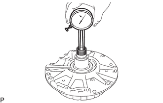
Using a caliper gauge, measure the inside diameter of the stator shaft assembly bushing.
- Standard Inside Diameter:
-
25.900 to 25.926 mm (1.0197 to 1.0207 in.)
If the inside diameter is not as specified, replace the stator shaft assembly.
35681A 4.INSPECT NO. 1 BRAKE DISC
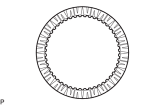
Check if the contact surfaces of the No. 1 brake discs, No. 1 brake plates and No. 1 brake flange are worn or burnt.
If necessary, replace them.
- NOTICE:
-
·
If the lining of any No. 1 brake disc is peeled or discolored, or even if part of a groove is damaged, replace all of the No. 1 brake discs.
·Before installing new No. 1 brake discs, soak them in ATF for at least 15 minutes.
35608J 5.INSPECT BRAKE PISTON RETURN SPRING SUB-ASSEMBLY (NO. 1 BRAKE)
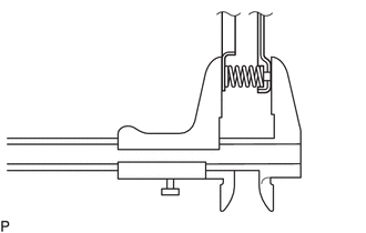
Using a vernier caliper, measure the free length of the brake piston return spring sub-assembly (No. 1 brake) including the spring seat.
- Standard Free Length:
-
15.16 mm (0.597 in.)
If the free length is less than the standard free length, replace the brake piston return spring sub-assembly (No. 1 brake).
35681A 6.INSPECT PISTON STROKE OF NO. 1 BRAKE
Inspect the piston stroke.
Using a dial indicator, measure the clearance (Dimension (A)) of the No. 1 brake at several points while applying compressed air (400 kPa (4.1 kgf/cm2, 58 psi)) to the oil hole as shown in the illustration, and calculate the average.
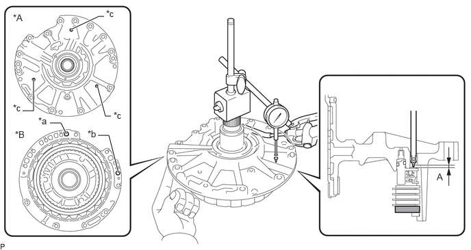
| *A | Front Side | *B | Rear Side |
| *a | Blow air into the oil hole | *b | Cover the oil hole |
| *c | Dial Indicator Insertion Hole | - | - |

|
No. 1 Brake Flange | - | - |
- Standard Clearance:
-
0.749 to 1.331 mm (0.0295 to 0.0524 in.)
- HINT:
-
The value is the average value obtained by measuring the dimension at 3 positions.
If the clearance is not as specified, check the installation condition, dimensions of each part and adjust the piston stroke.
Adjust the piston stroke.
Select the No. 1 brake flange and adjust the piston stroke value.
- Standard Clearance:
-
0.800 to 1.000 mm (0.0315 to 0.0393 in.)
- HINT:
-
There are 7 No. 1 brake flanges of different thicknesses.
- No. 1 Brake Flange Thickness:
-
Part No. Mark Thickness 35676-60260 0 5.45 to 5.55 mm (0.215 to 0.218 in.) 35676-60270 1 5.55 to 5.65 mm (0.219 to 0.222 in.) 35676-60280 2 5.65 to 5.75 mm (0.223 to 0.226 in.) 35676-60290 3 5.75 to 5.85 mm (0.227 to 0.230 in.) 35676-60300 4 5.85 to 5.95 mm (0.231 to 0.234 in.) 35676-60310 5 5.95 to 6.05 mm (0.235 to 0.238 in.) 35676-60320 6 6.05 to 6.15 mm (0.239 to 0.242 in.)
35706P 7.INSPECT FRONT PLANETARY SUN GEAR SUB-ASSEMBLY
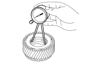
Using a caliper gauge, measure the inside diameter of the front planetary sun gear sub-assembly bushing.
- Standard Inside Diameter:
-
37.000 to 37.015 mm (1.4567 to 1.4572 in.)
If the inside diameter is not as specified, replace the front planetary sun gear sub-assembly.
35720 8.INSPECT FRONT PLANETARY GEAR ASSEMBLY
Using a feeler gauge, measure the clearance between the front planetary gear assembly and each pinion gear.
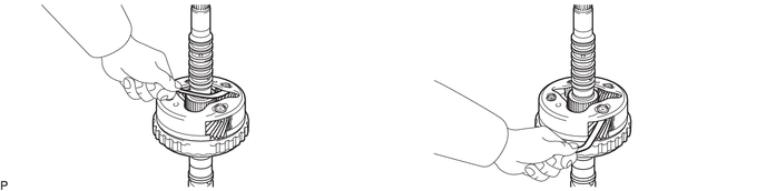
- Standard Clearance:
-
0.20 to 0.60 mm (0.00788 to 0.0236 in.)
If the clearance is not as specified, replace the front planetary gear assembly.
35650L 9.INSPECT PISTON STROKE OF C-2 CLUTCH ASSEMBLY
- NOTICE:
-
Do not disassemble the C-2 clutch assembly.
-
If disassembled, replace the C-2 clutch assembly with a new one.
Inspect the piston stroke.
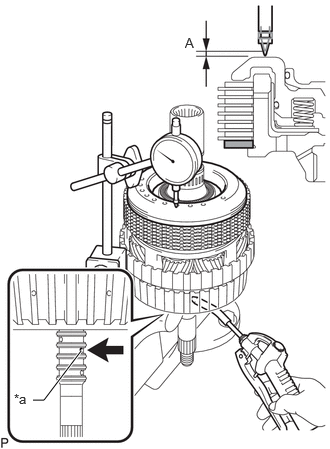
| *a | Blow air into the oil hole |
|
|
No. 2 Clutch Flange |
Using a dial indicator, measure the clearance (Dimension (A)) of the No. 2 clutch at several points while applying compressed air (400 kPa (4.1 kgf/cm2, 58 psi)) to the oil hole as shown in the illustration, and calculate the average.
- Standard Clearance:
-
0.962 to 1.758 mm (0.0379 to 0.0692 in.)
- HINT:
-
The value is the average value obtained by measuring the dimension at 3 positions.
If the clearance is not as specified, replace the C-2 clutch assembly.
35610 10.INSPECT PISTON STROKE OF C-1 CLUTCH ASSEMBLY
- NOTICE:
-
Do not disassemble the C-1 clutch assembly.
-
If disassembled, replace the C-1 clutch assembly with a new one.
Inspect the piston stroke.
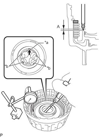
| *a | Blow air into the oil hole |
| *b | Cover the 4 oil holes |
|
|
No. 1 Clutch Flange |
Using a dial indicator, measure the clearance (Dimension (A)) of the No. 1 clutch at several points while applying compressed air (400 kPa (4.1 kgf/cm2, 58 psi)) to the oil hole as shown in the illustration, and calculate the average.
- Standard Clearance:
-
1.220 to 2.060 mm (0.0481 to 0.0811 in.)
- HINT:
-
The value is the average value obtained by measuring the dimension at 3 positions.
If the clearance is not as specified, replace the C-1 clutch assembly.
35610 11.INSPECT C-1 CLUTCH ASSEMBLY
- NOTICE:
-
Do not disassemble the C-1 clutch assembly.
-
If disassembled, replace the C-1 clutch assembly with a new one.
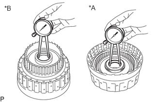
| *A | Front Side |
| *B | Rear Side |
Using a caliper gauge, measure the inside diameter of the C-1 clutch assembly bushing.
- Standard Inside Diameter (Front Side):
-
49.989 to 50.014 mm (1.9681 to 1.9690 in.)
- Standard Inside Diameter (Rear Side):
-
44.480 to 44.505 mm (1.7512 to 1.7521 in.)
If the inside diameter is not as specified, replace the C-1 clutch assembly.
35682A 12.INSPECT NO. 2 BRAKE DISC
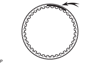
Check if the contact surfaces of the No. 2 brake discs, No. 2 brake plates and No. 2 brake flange are worn or burnt.
If necessary, replace them.
- NOTICE:
-
·
If the lining of any No. 2 brake disc is peeled or discolored, or even if part of the printed number is damaged, replace all the No. 2 brake discs.
·Before installing new No. 2 brake discs, soak them in ATF for at least 15 minutes.
35608J 13.INSPECT BRAKE PISTON RETURN SPRING SUB-ASSEMBLY (NO. 2 BRAKE)
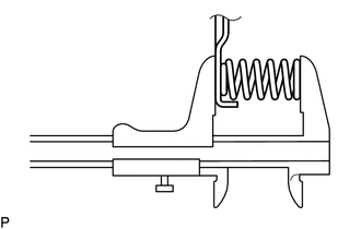
Using a vernier caliper, measure the free length of the brake piston return spring sub-assembly (No. 2 brake) including the spring seat.
- Standard Free Length:
-
18.11 mm (0.713 in.)
If the free length is less than the standard free length, replace the brake piston return spring sub-assembly (No. 2 brake).
35682A 14.INSPECT PISTON STROKE OF NO. 2 BRAKE
Inspect the piston stroke.
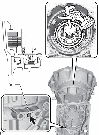
| *a | Blow air into the oil hole |
|
|
No. 2 Brake Flange |
Using a dial indicator, measure the clearance (Dimension (A)) of the No. 2 brake at several points while applying compressed air (200 kPa (2.0 kgf/cm2, 29 psi)) to the oil hole as shown in the illustration, and calculate the average.
- Standard Clearance:
-
0.605 to 1.395 mm (0.0239 to 0.0549 in.)
- HINT:
-
The value is the average value obtained by measuring the dimension at 3 positions.
If the clearance is not as specified, check the installation condition, dimensions of each part and adjust the piston stroke.
Adjust the piston stroke.
Select the No. 2 brake flange and adjust the piston stroke value.
- Standard Clearance:
-
0.900 to 1.100 mm (0.0355 to 0.0433 in.)
- HINT:
-
There are 9 No. 2 brake flanges of different thicknesses.
- No. 2 Brake Flange Thickness:
-
Part No. Mark Thickness 35678-60300 0 6.78 to 6.85 mm (0.267 to 0.269 in.) 35678-60310 1 6.85 to 6.95 mm (0.270 to 0.273 in.) 35678-60320 2 6.95 to 7.05 mm (0.274 to 0.277 in.) 35678-60330 3 7.05 to 7.15 mm (0.278 to 0.281 in.) 35678-60340 4 7.15 to 7.25 mm (0.282 to 0.285 in.) 35678-60350 5 7.25 to 7.35 mm (0.286 to 0.289 in.) 35678-60360 6 7.35 to 7.45 mm (0.290 to 0.293 in.) 35678-60370 7 7.45 to 7.55 mm (0.294 to 0.297 in.) 35678-60380 8 7.55 to 7.65 mm (0.298 to 0.301 in.)
35640 15.INSPECT PISTON STROKE OF NO. 3 CLUTCH
- NOTICE:
-
Do not disassemble the C-3 clutch assembly.
-
If disassembled, replace the C-3 clutch assembly with a new one.
Inspect the piston stroke.
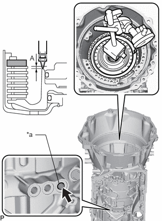
| *a | Blow air into the oil hole |
|
|
Clutch Flange |
Using a dial indicator, measure the clearance (Dimension (A)) of the No. 3 clutch at several points while applying compressed air (400 kPa (4.1 kgf/cm2, 58 psi)) to the oil hole as shown in the illustration, and calculate the average.
- Standard Clearance:
-
0.772 to 1.628 mm (0.0304 to 0.0640 in.)
- HINT:
-
The value is the average value obtained by measuring the dimension at 3 positions.
If the clearance is not as specified, replace the C-3 clutch assembly.
35620 16.INSPECT CENTER SUPPORT ASSEMBLY
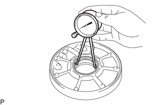
Using a caliper gauge, measure the inside diameter of the center support assembly bushing.
- Standard Inside Diameter:
-
73.082 to 73.121 mm (2.8773 to 2.8787 in.)
If the inside diameter is not as specified, replace the center support assembly.
35750 17.INSPECT CENTER PLANETARY GEAR ASSEMBLY
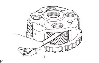
Using a feeler gauge, measure the clearance between the center planetary gear assembly and each pinion gear.
- Standard Clearance:
-
0.20 to 0.67 mm (0.00788 to 0.02637 in.)
If the clearance is not as specified, replace the center planetary gear assembly.
35706H 18.INSPECT PLANETARY SUN GEAR SUB-ASSEMBLY
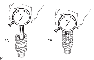
| *A | Front Side |
| *B | Rear Side |
Using a caliper gauge, measure the inside diameter of the planetary sun gear sub-assembly bushing.
- Standard Inside Diameter (Front Side and Rear Side):
-
30.600 to 30.621 mm (1.2048 to 1.2055 in.)
If the inside diameter is not as specified, replace the planetary sun gear sub-assembly.
35760 19.INSPECT REAR PLANETARY GEAR ASSEMBLY
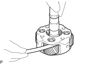
Using a feeler gauge, measure the clearance between the rear planetary gear assembly and each pinion gear.
- Standard Clearance:
-
0.20 to 0.64 mm (0.00788 to 0.02519 in.)
If the clearance is not as specified, replace the rear planetary gear assembly.
35883C 20.INSPECT NO. 4 CLUTCH DISC
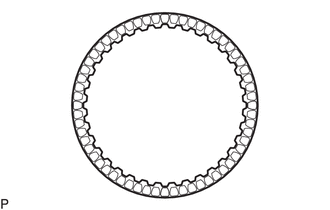
Check if the contact surfaces of the No. 4 clutch discs, No. 4 clutch plates and clutch flange are worn or burnt.
If necessary, replace them.
- NOTICE:
-
·
If the lining of any No. 4 clutch disc is peeled or discolored, or even if part of a groove is damaged, replace all of the No. 4 clutch discs.
·Before installing new No. 4 clutch discs, soak them in ATF for at least 15 minutes.
35603A 21.INSPECT FORWARD CLUTCH RETURN SPRING SUB-ASSEMBLY (C-4 CLUTCH)
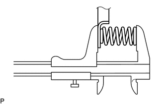
Using a vernier caliper, measure the free length of the forward clutch return spring sub-assembly (C-4 clutch) including the spring seat.
- Standard Free Length:
-
21.41 mm (0.843 in.)
If the free length is less than the standard free length, replace the forward clutch return spring sub-assembly (C-4 clutch).
22.INSPECT PISTON STROKE OF NO. 4 CLUTCH
Inspect the piston stroke.
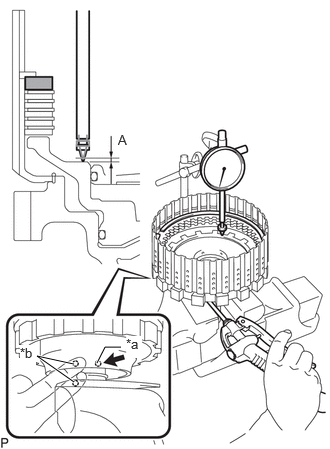
| *a | Blow air into the oil hole |
| *b | Cover the 2 oil holes |
|
|
Clutch Flange |
Using a dial indicator, measure the clearance (Dimension (A)) of the No. 4 clutch at several points while applying compressed air (400 kPa (4.1 kgf/cm2, 58 psi)) to the oil hole as shown in the illustration, and calculate the average.
- Standard Clearance:
-
0.571 to 1.429 mm (0.0225 to 0.0562 in.)
- HINT:
-
The value is the average value obtained by measuring the dimension at 3 positions.
If the clearance is not as specified, check the installation condition, dimensions of each part and adjust the piston stroke.
Adjust the piston stroke.
Select the clutch flange and adjust the piston stroke value.
- Standard Clearance:
-
0.900 to 1.100 mm (0.0355 to 0.0433 in.)
- HINT:
-
There are 9 clutch flanges of different thicknesses.
- Clutch Flange Thickness:
-
Part No. Thickness 35635-60510 4.25 to 4.35 mm (0.168 to 0.171 in.) 35635-60520 4.35 to 4.45 mm (0.172 to 0.175 in.) 35635-60530 4.45 to 4.55 mm (0.176 to 0.179 in.) 35635-60540 4.55 to 4.65 mm (0.180 to 0.183 in.) 35635-60550 4.65 to 4.75 mm (0.184 to 0.187 in.) 35635-60560 4.75 to 4.85 mm (0.188 to 0.190 in.) 35635-60570 4.85 to 4.95 mm (0.191 to 0.194 in.) 35635-60580 4.95 to 5.05 mm (0.195 to 0.198 in.) 35635-60590 5.05 to 5.15 mm (0.199 to 0.202 in.)
23.INSPECT INDIVIDUAL PISTON OPERATION
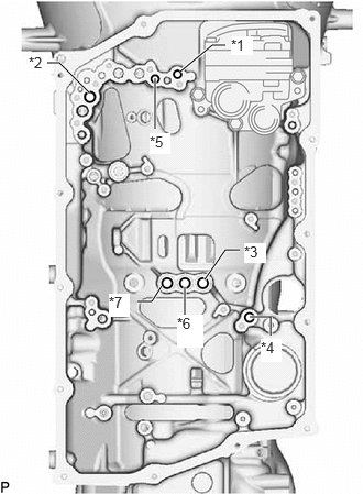
| *1 | No. 1 Clutch (C-1) |
| *2 | No. 2 Clutch (C-2) |
| *3 | No. 3 Clutch (C-3) |
| *4 | No. 4 Clutch (C-4) |
| *5 | No. 1 Brake (B-1) |
| *6 | No. 2 Brake (B-2 (In)) |
| *7 | No. 2 Brake (B-2 (Out)) |
Check the operating sound of each piston while applying compressed air to each oil hole shown in the illustration.
35104 24.INSPECT AUTOMATIC TRANSMISSION CASE SUB-ASSEMBLY
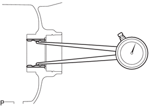
Using a caliper gauge, measure the inside diameter of the automatic transmission case sub-assembly sleeve bushing.
- Standard Free Length:
-
48.370 to 48.455 mm (1.9044 to 1.9076 in.)
If the inside diameter is not as specified, replace the automatic transmission case sub-assembly.