V35A-FTS ENGINE CONTROL CAMSHAFT OIL CONTROL SOLENOID(for Bank 2) INSPECTION
PROCEDURE

 15370C 1.INSPECT CAM TIMING OIL CONTROL SOLENOID ASSEMBLY LH (for Intake Side of Bank 2)
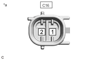
| *a | Component without harness connected (Cam Timing Oil Control Solenoid Assembly LH) (for Intake Side of Bank 2) |
Check the resistance.
Measure the resistance according to the value(s) in the table below.
- Standard Resistance:
-
Tester Connection Condition Specified Condition Click Location & Routing(C16)Location & Routingewd_type=routing;type=c;code=C16
C16-1 - C16-2 0 °C (32 °F) 6.3 to 7.3 Ω C16-1 - C16-2 20 °C (68 °F) 6.9 to 7.9 Ω C16-1 - C16-2 40 °C (104 °F) 7.4 to 8.6 Ω
If the result is not as specified, replace the cam timing oil control solenoid assembly LH (for Intake Side of Bank 2).
Stroke amount inspection
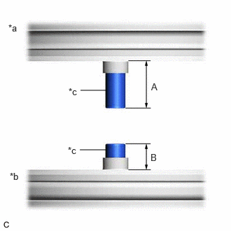
| *a | Shaft Side Facing Down |
| *b | Shaft Side Facing Up |
| *c | Shaft |
Using a vernier caliper, measure length (A) and (B) with the shaft of the cam timing oil control solenoid assembly LH (for Intake Side of Bank 2) set in the respective positions shown in the illustration.
- NOTICE:
-
Do not apply battery voltage to the terminals of the cam timing oil control solenoid assembly LH (for Intake Side of Bank 2).
- HINT:
-
If the shaft does not extend under its own weight, extend the shaft with your fingers.
Calculate the stroke amount based on the difference of length (A) and (B).
- Standard:
-
4.3 mm (0.170 in.) or more
- HINT:
-
Stroke amount = length (A) - length (B)
If the value is not as specified, replace the cam timing oil control solenoid assembly LH (for Intake Side of Bank 2).
15370C 2.INSPECT CAM TIMING OIL CONTROL SOLENOID ASSEMBLY LH (for Exhaust Side of Bank 2)
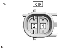
| *a | Component without harness connected (Cam Timing Oil Control Solenoid Assembly LH) (for Exhaust Side of Bank 2) |
Check the resistance.
Measure the resistance according to the value(s) in the table below.
- Standard Resistance:
-
Tester Connection Condition Specified Condition Click Location & Routing(C19)Location & Routingewd_type=routing;type=c;code=C19
C19-1 - C19-2 0 °C (32 °F) 6.3 to 7.3 Ω C19-1 - C19-2 20 °C (68 °F) 6.9 to 7.9 Ω C19-1 - C19-2 40 °C (104 °F) 7.4 to 8.6 Ω
If the result is not as specified, replace the cam timing oil control solenoid assembly LH (for Exhaust Side of Bank 2).
Stroke amount inspection
| *a | Shaft Side Facing Down |
| *b | Shaft Side Facing Up |
| *c | Shaft |
Using a vernier caliper, measure length (A) and (B) with the shaft of the cam timing oil control solenoid assembly LH (for Exhaust Side of Bank 2) set in the respective positions shown in the illustration.
- NOTICE:
-
Do not apply battery voltage to the terminals of the cam timing oil control solenoid assembly LH (for Exhaust Side of Bank 2).
- HINT:
-
If the shaft does not extend under its own weight, extend the shaft with your fingers.
Calculate the stroke amount based on the difference of length (A) and (B).
- Standard:
-
4.3 mm (0.170 in.) or more
- HINT:
-
Stroke amount = length (A) - length (B)
If the value is not as specified, replace the cam timing oil control solenoid assembly LH (for Exhaust Side of Bank 2).