RM38G0E _51 Engine / Hybrid System _100526 V35A-FTS ENGINE CONTROL _0467372 KNOCK SENSOR G
V35A-FTS ENGINE CONTROL KNOCK SENSOR INSPECTION
PROCEDURE

 89615 1.INSPECT KNOCK CONTROL SENSOR
a.
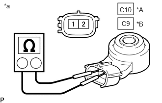
2.5,0.063 2.833,0.313 0.333,0.25 2.5,0.375 2.833,0.625 0.333,0.25 0.083,0.042 0.396,0.24 0.313,0.198 10 false *a 2.896,0.125 3.406,0.396 0.51,0.271 10 false *A 2.542,0.125 3.052,0.396 0.51,0.271 10 false C10 2.896,0.427 3.406,0.698 0.51,0.271 10 false *B 2.583,0.417 3.094,0.688 0.51,0.271 10 false C9
| *A | for Bank 1 |
| *B | for Bank 2 |
| *a | Component without harness connected (Knock Control Sensor) |
Measure the resistance according to the value(s) in the table below.
- Standard Resistance (for Bank 1):
-
Tester Connection Condition Specified Condition Click Location & Routing(C10)Location & Routingewd_type=routing;type=c;code=C10
C10-1 - C10-2 25°C (77°F) 120 to 280 kΩ
- Standard Resistance (for Bank 2):
-
Tester Connection Condition Specified Condition Click Location & Routing(C9)Location & Routingewd_type=routing;type=c;code=C9
C9-1 - C9-2 25°C (77°F) 120 to 280 kΩ
If the result is not as specified, replace the knock control sensor.