Home › Engine / Hybrid System › V35A-FTS (ENGINE CONTROL) › AIR FUEL RATIO SENSOR
RM38G0E _51 Engine / Hybrid System _100526 V35A-FTS ENGINE CONTROL _0467375 AIR FUEL RATIO SENSOR G

V35A-FTS ENGINE CONTROL  AIR FUEL RATIO SENSOR  INSPECTION  


PROCEDURE

Hide 89467B 1.INSPECT AIR FUEL RATIO SENSOR
a.
A486450C03
1.542,0.156 1.885,0.354 0.344,0.198 0.99,0.802 1.333,0.802 true 2.073,1.333 2.417,1.333 true 1.01,1.333 1.354,1.333 true 2.073,0.823 2.417,0.823 true 0.729,0.729 1.073,1.063 0.344,0.333 10 false +B 2.5,0.729 3.083,0.896 0.583,0.167 10 false HA2A 2.5,1.25 3.135,1.469 0.635,0.219 10 false A2A+ 0.615,1.25 1.156,1.458 0.542,0.208 10 false A2A- 0.073,0.063 0.417,0.396 0.344,0.333 10 false *a 1.604,0.188 1.938,0.438 0.333,0.25 10 false C30
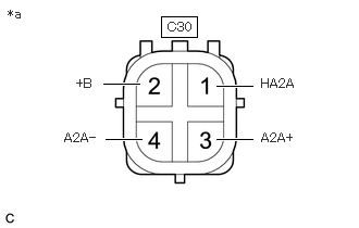
*a Component without harness connected
(Air Fuel Ratio Sensor)


Measure the resistance according to the value(s) in the table below.

Standard Resistance:
Tester Connection Condition Specified Condition

Click Location & Routing(C30)Location & Routing

Click Connector(C30)Engine Compartment>Connecting Wire / Cooling Fan Wire / Engine Wire / Fuel Pump Motor Wire / No. 1 Connecting Wire / No. 10 Engine Wire / No. 2 Connecting Wire / No. 3 Connecting Wire / No. 4 Connecting Wire / Sensor Wire / Turbocharger Wire>Air Fuel Ratio Sensor (Bank 2 Sensor 1)

C30-1 (HA2A) - C30-2 (+B) 20°C (68°F) 1.4 to 3.0 Ω
C30-3 (A2A+) - C30-4 (A2A-) Always 10 kΩ or higher


If the result is not as specified, replace the air fuel ratio sensor.


Hide 89467C 2.INSPECT NO. 2 AIR FUEL RATIO SENSOR
a.
A486450C01
1.542,0.156 1.885,0.354 0.344,0.198 1,0.813 1.344,0.813 true 2.073,1.333 2.417,1.333 true 1,1.333 1.344,1.333 true 2.073,0.823 2.417,0.823 true 0.76,0.729 1.104,1.063 0.344,0.333 10 false +B 2.479,0.729 3.063,0.896 0.583,0.167 10 false HA1A 2.479,1.25 3.115,1.469 0.635,0.219 10 false A1A+ 0.667,1.25 1.208,1.458 0.542,0.208 10 false A1A- 0.073,0.063 0.417,0.396 0.344,0.333 10 false *a 1.604,0.188 1.938,0.438 0.333,0.25 10 false C29
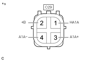
*a Component without harness connected
(No. 2 Air Fuel Ratio Sensor)


Measure the resistance according to the value(s) in the table below.

Standard Resistance:
Tester Connection Condition Specified Condition

Click Location & Routing(C29)Location & Routing

Click Connector(C29)Engine Compartment>Connecting Wire / Cooling Fan Wire / Engine Wire / Fuel Pump Motor Wire / No. 1 Connecting Wire / No. 10 Engine Wire / No. 2 Connecting Wire / No. 3 Connecting Wire / No. 4 Connecting Wire / Sensor Wire / Turbocharger Wire>Air Fuel Ratio Sensor (Bank 1 Sensor 1)

C29-1 (HA1A) - C29-2 (+B) 20°C (68°F) 1.4 to 3.0 Ω
C29-3 (A1A+) - C29-4 (A1A-) Always 10 kΩ or higher


If the result is not as specified, replace the No. 2 air fuel ratio sensor.


Hide 89467D 3.INSPECT NO. 3 AIR FUEL RATIO SENSOR
a.
A486450C04
1.552,0.156 1.896,0.354 0.344,0.198 0.99,0.813 1.333,0.813 true 2.083,1.313 2.427,1.313 true 1,1.323 1.344,1.323 true 2.083,0.813 2.427,0.813 true 0.75,0.74 1.094,1.073 0.344,0.333 10 false +B 2.49,0.719 3.063,1.052 0.573,0.333 10 false HA2B 2.479,1.229 3.333,1.615 0.854,0.385 10 false A2B+ 0.646,1.25 1.25,1.573 0.604,0.323 10 false A2B- 0.073,0.063 0.417,0.396 0.344,0.333 10 false *a 1.604,0.177 1.938,0.427 0.333,0.25 10 false C32
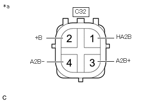
*a Component without harness connected
(No. 3 Air Fuel Ratio Sensor)


Measure the resistance according to the value(s) in the table below.

Standard Resistance:
Tester Connection Condition Specified Condition

Click Location & Routing(C32)Location & Routing

Click Connector(C32)Engine Compartment>Connecting Wire / Cooling Fan Wire / Engine Wire / Fuel Pump Motor Wire / No. 1 Connecting Wire / No. 10 Engine Wire / No. 2 Connecting Wire / No. 3 Connecting Wire / No. 4 Connecting Wire / Sensor Wire / Turbocharger Wire>Air Fuel Ratio Sensor (Bank 2 Sensor 2)

C32-1 (HA2B) - C32-2 (+B) 20°C (68°F) 2 to 6 Ω
C32-3 (A2B+) - C32-4 (A2B-) Always 10 kΩ or higher


If the result is not as specified, replace the No. 3 air fuel ratio sensor.


Hide 89467E 4.INSPECT NO. 4 AIR FUEL RATIO SENSOR
a.
A486450C02
1.552,0.167 1.896,0.365 0.344,0.198 1.01,0.823 1.354,0.823 true 2.063,1.333 2.406,1.333 true 1,1.333 1.344,1.333 true 2.083,0.823 2.427,0.823 true 0.75,0.729 1.094,1.063 0.344,0.333 10 false +B 2.5,0.729 3.073,1.063 0.573,0.333 10 false HA1B 2.49,1.25 3.344,1.635 0.854,0.385 10 false A1B+ 0.656,1.25 1.26,1.573 0.604,0.323 10 false A1B- 0.073,0.063 0.417,0.396 0.344,0.333 10 false *a 1.604,0.177 1.938,0.427 0.333,0.25 10 false C31
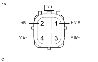
*a Component without harness connected
(No. 4 Air Fuel Ratio Sensor)


Measure the resistance according to the value(s) in the table below.

Standard Resistance:
Tester Connection Condition Specified Condition

Click Location & Routing(C31)Location & Routing

Click Connector(C31)Engine Compartment>Connecting Wire / Cooling Fan Wire / Engine Wire / Fuel Pump Motor Wire / No. 1 Connecting Wire / No. 10 Engine Wire / No. 2 Connecting Wire / No. 3 Connecting Wire / No. 4 Connecting Wire / Sensor Wire / Turbocharger Wire>Air Fuel Ratio Sensor (Bank 1 Sensor 2)

C31-1 (HA1B) - C31-2 (+B) 20°C (68°F) 2 to 6 Ω
C31-3 (A1B+) - C31-4 (A1B-) Always 10 kΩ or higher


If the result is not as specified, replace the No. 4 air fuel ratio sensor.