1GR-FE ENGINE CONTROL CAMSHAFT OIL CONTROL VALVE INSPECTION
PROCEDURE

 15330B 1.INSPECT CAMSHAFT TIMING OIL CONTROL VALVE ASSEMBLY RH
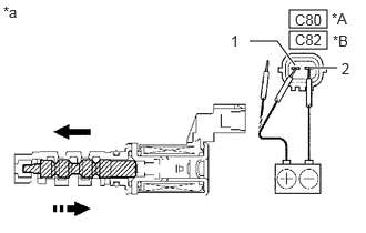
| *A | for Intake |
| *B | for Exhaust |
| *a | Component without harness connected (Camshaft Timing Oil Control Valve Assembly RH) |
Measure the resistance according to the value(s) in the table below.
- Standard Resistance (for Intake):
-
Tester Connection Condition Specified Condition Click Location & Routing(C80)Location & Routingewd_type=routing;type=c;code=C80
C80-1 - C80-2 20°C (68°F) 6.9 to 7.9 Ω
- Standard Resistance (for Exhaust):
-
Tester Connection Condition Specified Condition Click Location & Routing(C82)Location & Routingewd_type=routing;type=c;code=C82
C82-1 - C82-2 20°C (68°F) 6.9 to 7.9 Ω
If the result is not as specified, replace the camshaft timing oil control valve assembly RH.
Connect the positive (+) lead of the battery to terminal 1 and the negative (-) lead to terminal 2 and check the movement of the valve.
- OK:
-
Condition Specified Condition Battery positive (+) voltage is applied Valve moves in direction of left arrow shown in illustration Battery positive (+) voltage is cut off Valve moves in direction of right arrow shown in illustration
If the result is not as specified, replace the camshaft timing oil control valve assembly RH.
- HINT:
-
If the camshaft timing oil control valve assembly RH cannot return properly because of foreign matter, a small pressure leak in the advanced direction may occur and a DTC may be stored.
15340 2.INSPECT CAMSHAFT TIMING OIL CONTROL VALVE ASSEMBLY LH
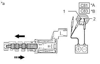
| *A | for Intake |
| *B | for Exhaust |
| *a | Component without harness connected (Camshaft Timing Oil Control Valve Assembly LH) |
Measure the resistance according to the value(s) in the table below.
- Standard Resistance (for Intake):
-
Tester Connection Condition Specified Condition Click Location & Routing(C81)Location & Routingewd_type=routing;type=c;code=C81
C81-1 - C81-2 20°C (68°F) 6.9 to 7.9 Ω
- Standard Resistance (for Exhaust):
-
Tester Connection Condition Specified Condition Click Location & Routing(C83)Location & Routingewd_type=routing;type=c;code=C83
C83-1 - C83-2 20°C (68°F) 6.9 to 7.9 Ω
If the result is not as specified, replace the camshaft timing oil control valve assembly LH.
Connect the positive (+) lead of the battery to terminal 1 and the negative (-) lead to terminal 2 and check the movement of the valve.
- OK:
-
Condition Specified Condition Battery positive (+) voltage is applied Valve moves in direction of left arrow shown in illustration Battery positive (+) voltage is cut off Valve moves in direction of right arrow shown in illustration
If the result is not as specified, replace the camshaft timing oil control valve assembly LH.
- HINT:
-
If the camshaft timing oil control valve assembly LH cannot return properly because of foreign matter, a small pressure leak in the advanced direction may occur and a DTC may be stored.