SEAT FRONT POWER SEAT CONTROL SYSTEM(w/ Memory) B2658 Short in Sensor with Motor Power Supply Circuit
DESCRIPTION
This DTC is stored when a power seat motor operates (a position control sensor is being supplied with power) and the power supply voltage does not rise to the specified value.
| DTC No. | Detection Item | DTC Detection Condition | Trouble Area | DTC Output from | Priority |
|---|---|---|---|---|---|
| B2658 | Short in Sensor with Motor Power Supply Circuit | Problem with the voltage supplied to the position control sensor. |
·
Position control ECU assembly
·
Slide motor (front seat adjuster assembly LH) (for LHD)
·
Slide motor (front seat adjuster assembly RH) (for RHD)
·
Front vertical motor (front seat adjuster assembly LH) (for LHD)
·
Front vertical motor (front seat adjuster assembly RH) (for RHD)
·
Lifter motor (front seat adjuster assembly LH) (for LHD)
·
Lifter motor (front seat adjuster assembly RH) (for RHD)
·
Reclining motor (front seatback frame sub-assembly LH) (for LHD)
·
Reclining motor (front seatback frame sub-assembly RH) (for RHD)
·
Harness or connector |
Driver Seat | B |
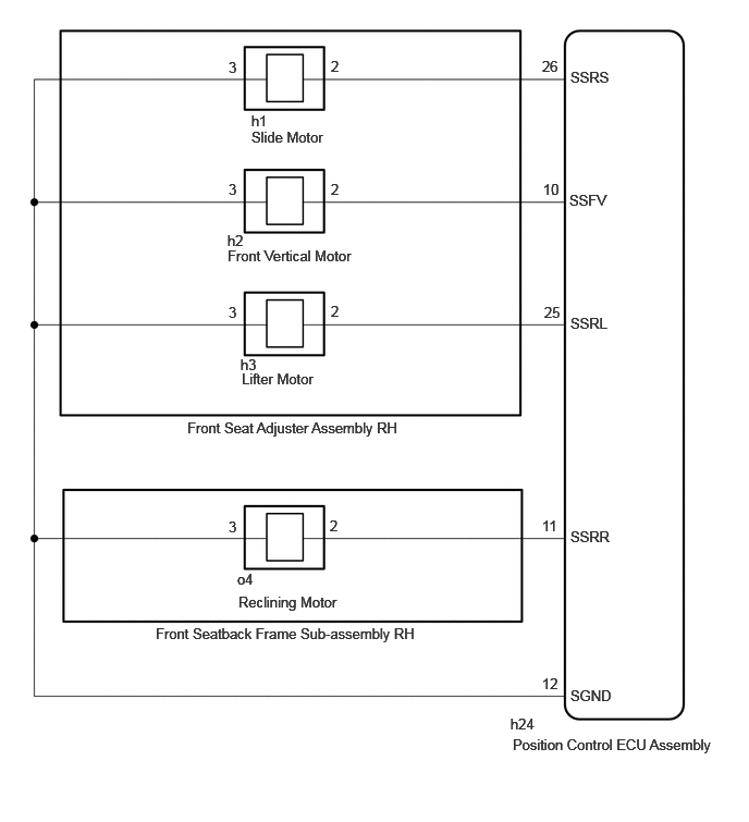
WIRING DIAGRAM
for LHD:
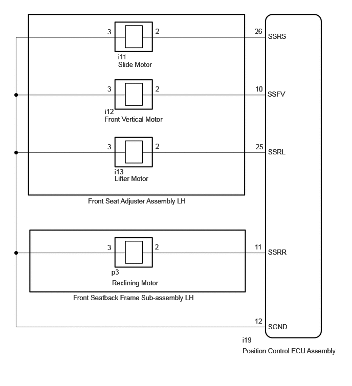
for RHD:
CAUTION / NOTICE / HINT
- NOTICE:
-
Initializing the position control ECU assembly will clear the seat position memory.
- HINT:
-
Make sure to initialize the position control ECU assembly after replacing the seat assembly or any related parts (including removal and installation).
-
Click hereVehicle Interior>SEAT>FRONT POWER SEAT CONTROL SYSTEM (w/ Memory)>REGISTRATION
PROCEDURE
Check the vehicle type.
- Result:
-
Result Proceed to for LHD A for RHD B
A
B
Clear the DTCs.
- Body Electrical > Driver Seat > Clear DTCs
- 50002 162
- Result:
-
Proceed to NEXT
NEXT
Check for DTCs.
- Body Electrical > Driver Seat > Trouble Codes
- 50001 162
- Result:
-
Result Proceed to B2658 is not output A B2658 is output B
A
Click hereGeneral>INTRODUCTION>HOW TO TROUBLESHOOT ECU CONTROLLED SYSTEMS>HOW TO PROCEED WITH TROUBLESHOOTING
B
Pre-procedure1
Disconnect the i19 position control ECU assembly connector.
Disconnect the i11 slide motor (front seat adjuster assembly LH) connector.
Procedure1
Measure the resistance according to the value(s) in the table below.
- Standard Resistance:
-
Tester Connection Condition Specified Condition Click Location & Routing(i19,i11)Location & Routingewd_type=routing;type=c,c;code=i19,i11
Click Connector(i19)Seat>Front Seat Wire LH>Front Position Control ECU Assembly LHewd_type=component;type=c;code=i19;pinno=26,12
Click Connector(i11)Seat>Front Seat Wire LH>Power Seat Slide Motor LH (Front Seat Adjuster Assembly LH)ewd_type=component;type=c;code=i11;pinno=2,3
i19-26 (SSRS) - i11-2 Always Below 1 Ω i19-26 (SSRS) or i11-2 - Body ground Always 10 kΩ or higher i19-12 (SGND) - i11-3 Always Below 1 Ω i19-12 (SGND) or i11-3 - Body ground Always 10 kΩ or higher
- Result:
-
Proceed to OK NG
Post-procedure1
None
OK
NG
Pre-procedure1
Disconnect the i11 slide motor (front seat adjuster assembly LH) connector.
Procedure1
Measure the voltage according to the value(s) in the table below.
- Standard Voltage:
-
Tester Connection Condition Specified Condition Click Location & Routing(i11)Location & Routingewd_type=routing;type=c;code=i11
Click Connector(i11)Seat>Front Seat Wire LH>Power Seat Slide Motor LH (Front Seat Adjuster Assembly LH)ewd_type=component;type=c;code=i11;pinno=2,3
i11-2 - i11-3 Slide switch on 4.8 to 5.1 V
- Result:
-
Proceed to OK NG
Post-procedure1
None
OK
NG
Pre-procedure1
Disconnect the i11 slide motor (front seat adjuster assembly LH) connector.
Clear the DTCs.
- Body Electrical > Driver Seat > Clear DTCs
- 50002 162
Procedure1
Check the DTCs.
- Body Electrical > Driver Seat > Trouble Codes
- 50001 162
- Result:
-
Result Proceed to B2658 is output A B2658 is not output B
Post-procedure1
None
A
B
Pre-procedure1
Disconnect the i19 position control ECU assembly connector.
Disconnect the i12 front vertical motor (power seat tilt motor assembly LH) connector.
Procedure1
Measure the resistance according to the value(s) in the table below.
- Standard Resistance:
-
Tester Connection Condition Specified Condition Click Location & Routing(i19,i12)Location & Routingewd_type=routing;type=c,c;code=i19,i12
Click Connector(i19)Seat>Front Seat Wire LH>Front Position Control ECU Assembly LHewd_type=component;type=c;code=i19;pinno=10,12
Click Connector(i12)Seat>Front Seat Wire LH>Power Seat Tilt Motor LH (Front Seat Adjuster Assembly LH)ewd_type=component;type=c;code=i12;pinno=2,3
i19-10 (SSFV) - i12-2 Always Below 1 Ω i19-10 (SSFV) or i12-2 - Body ground Always 10 kΩ or higher i19-12 (SGND) - i12-3 Always Below 1 Ω i19-12 (SGND) or i12-3 - Body ground Always 10 kΩ or higher
- Result:
-
Proceed to OK NG
Post-procedure1
None
OK
NG
Pre-procedure1
Disconnect the i12 front vertical motor (front seat adjuster assembly LH) connector.
Procedure1
Measure the voltage according to the value(s) in the table below.
- Standard Voltage:
-
Tester Connection Condition Specified Condition Click Location & Routing(i12)Location & Routingewd_type=routing;type=c;code=i12
Click Connector(i12)Seat>Front Seat Wire LH>Power Seat Tilt Motor LH (Front Seat Adjuster Assembly LH)ewd_type=component;type=c;code=i12;pinno=2,3
i12-2 - i12-3 Front vertical switch on 4.8 to 5.1 V
- Result:
-
Proceed to OK NG
Post-procedure1
None
OK
NG
Pre-procedure1
Disconnect the i12 front vertical motor (front seat adjuster assembly LH) connector.
Clear the DTCs.
- Body Electrical > Driver Seat > Clear DTCs
- 50002 162
Procedure1
Check the DTCs.
- Body Electrical > Driver Seat > Trouble Codes
- 50001 162
- Result:
-
Result Proceed to B2658 is output A B2658 is not output B
Post-procedure1
None
A
B
Pre-procedure1
Disconnect the i19 position control ECU assembly connector.
Disconnect the i13 lifter motor (front seat adjuster assembly) connector.
Procedure1
Measure the resistance according to the value(s) in the table below.
- Standard Resistance:
-
Tester Connection Condition Specified Condition Click Location & Routing(i19,i13)Location & Routingewd_type=routing;type=c,c;code=i19,i13
Click Connector(i19)Seat>Front Seat Wire LH>Front Position Control ECU Assembly LHewd_type=component;type=c;code=i19;pinno=25,12
Click Connector(i13)Seat>Front Seat Wire LH>Power Seat Lifter Motor LH (Front Seat Adjuster Assembly LH)ewd_type=component;type=c;code=i13;pinno=2,3
i19-25 (SSRL) - i13-2 Always Below 1 Ω i19-25 (SSRL) or i13-2 - Body ground Always 10 kΩ or higher i19-12 (SGND) - i13-3 Always Below 1 Ω i19-12 (SGND) or i13-3 - Body ground Always 10 kΩ or higher
- Result:
-
Proceed to OK NG
Post-procedure1
None
OK
NG
Pre-procedure1
Disconnect the i13 lifter motor (front seat adjuster assembly) connector.
Procedure1
Measure the voltage according to the value(s) in the table below.
- Standard Voltage:
-
Tester Connection Condition Specified Condition Click Location & Routing(i13)Location & Routingewd_type=routing;type=c;code=i13
Click Connector(i13)Seat>Front Seat Wire LH>Power Seat Lifter Motor LH (Front Seat Adjuster Assembly LH)ewd_type=component;type=c;code=i13;pinno=2,3
i13-2 - i13-3 Lifter switch on 4.8 to 5.1 V
- Result:
-
Proceed to OK NG
Post-procedure1
None
OK
NG
Pre-procedure1
Disconnect the i13 lifter motor (front seat adjuster assembly LH) connector.
Clear the DTCs.
- Body Electrical > Driver Seat > Clear DTCs
- 50002 162
Procedure1
Check the DTCs.
- Body Electrical > Driver Seat > Trouble Codes
- 50001 162
- Result:
-
Result Proceed to B2658 is output A B2658 is not output B
Post-procedure1
None
A
B
Pre-procedure1
Disconnect the i19 position control ECU assembly connector.
Disconnect the p3 reclining motor (front seatback frame sub-assembly LH) connector.
Procedure1
Measure the resistance according to the value(s) in the table below.
- Standard Resistance:
-
Tester Connection Condition Specified Condition Click Location & Routing(i19,p3)Location & Routingewd_type=routing;type=c,c;code=i19,p3
Click Connector(i19)Seat>Front Seat Wire LH>Front Position Control ECU Assembly LHewd_type=component;type=c;code=i19;pinno=11,12
Click Connector(p3)Seat>No. 2 Front Seat Wire LH>Front Power Seat Reclining Motor LHewd_type=component;type=c;code=p3;pinno=2,3
i19-11 (SSRR) - p3-2 Always Below 1 Ω i19-11 (SSRR) or p3-2 - Body ground Always 10 kΩ or higher i19-12 (SGND) - p3-3 Always Below 1 Ω i19-12 (SGND) or p3-3 - Body ground Always 10 kΩ or higher
- Result:
-
Proceed to OK NG
Post-procedure1
None
OK
NG
Pre-procedure1
Reconnect the p3 reclining motor (front seatback frame sub-assembly LH) connector.
Procedure1
Measure the voltage according to the value(s) in the table below.
- Standard Voltage:
-
Tester Connection Condition Specified Condition Click Location & Routing(p3)Location & Routingewd_type=routing;type=c;code=p3
Click Connector(p3)Seat>No. 2 Front Seat Wire LH>Front Power Seat Reclining Motor LHewd_type=component;type=c;code=p3;pinno=2,3
p3-2 - p3-3 Reclining switch on 4.8 to 5.1 V
- Result:
-
Proceed to OK NG
Post-procedure1
None
OK
NG
Pre-procedure1
Disconnect the p3 reclining motor (front seatback frame sub-assembly LH) connector.
Clear the DTCs.
- Body Electrical > Driver Seat > Clear DTCs
- 50002 162
Procedure1
Check the DTCs.
- Body Electrical > Driver Seat > Trouble Codes
- 50001 162
- Result:
-
Result Proceed to B2658 is output A B2658 is not output B
Post-procedure1
None
A
B
Clear the DTCs.
- Body Electrical > Driver Seat > Clear DTCs
- 50002 162
- Result:
-
Proceed to NEXT
NEXT
Check for DTCs.
- Body Electrical > Driver Seat > Trouble Codes
- 50001 162
- Result:
-
Result Proceed to B2658 is not output A B2658 is output B
A
Click hereGeneral>INTRODUCTION>HOW TO TROUBLESHOOT ECU CONTROLLED SYSTEMS>HOW TO PROCEED WITH TROUBLESHOOTING
B
Pre-procedure1
Disconnect the h24 position control ECU assembly connector.
Disconnect the h1 slide motor (front seat adjuster assembly RH) connector.
Procedure1
Measure the resistance according to the value(s) in the table below.
- Standard Resistance:
-
Tester Connection Condition Specified Condition Click Location & Routing(h24,h1)Location & Routingewd_type=routing;type=c,c;code=h24,h1
Click Connector(h24)Seat>Front Seat Wire RH>Front Position Control ECU Assembly RHewd_type=component;type=c;code=h24;pinno=26,12
Click Connector(h1)Seat>Front Seat Wire RH>Power Seat Slide Motor RH (Front Seat Adjuster Assembly RH)ewd_type=component;type=c;code=h1;pinno=2,3
h24-26 (SSRS) - h1-2 Always Below 1 Ω h24-26 (SSRS) or h1-2 - Body ground Always 10 kΩ or higher h24-12 (SGND) - h1-3 Always Below 1 Ω h24-12 (SGND) or h1-3 - Body ground Always 10 kΩ or higher
- Result:
-
Proceed to OK NG
Post-procedure1
None
OK
NG
Pre-procedure1
Disconnect the h1 slide motor (front seat adjuster assembly RH) connector.
Procedure1
Measure the voltage according to the value(s) in the table below.
- Standard Voltage:
-
Tester Connection Condition Specified Condition Click Location & Routing(h1)Location & Routingewd_type=routing;type=c;code=h1
Click Connector(h1)Seat>Front Seat Wire RH>Power Seat Slide Motor RH (Front Seat Adjuster Assembly RH)ewd_type=component;type=c;code=h1;pinno=2,3
h1-2 - h1-3 Slide switch on 4.8 to 5.1 V
- Result:
-
Proceed to OK NG
Post-procedure1
None
OK
NG
Pre-procedure1
Disconnect the h1 slide motor (front seat adjuster assembly RH) connector.
Clear the DTCs.
- Body Electrical > Driver Seat > Clear DTCs
- 50002 162
Procedure1
Check the DTCs.
- Body Electrical > Driver Seat > Trouble Codes
- 50001 162
- Result:
-
Result Proceed to B2658 is output A B2658 is not output B
Post-procedure1
None
A
B
Pre-procedure1
Disconnect the h24 position control ECU assembly connector.
Disconnect the h2 front vertical motor (front seat adjuster assembly RH) connector.
Procedure1
Measure the resistance according to the value(s) in the table below.
- Standard Resistance:
-
Tester Connection Condition Specified Condition Click Location & Routing(h24,h2)Location & Routingewd_type=routing;type=c,c;code=h24,h2
Click Connector(h24)Seat>Front Seat Wire RH>Front Position Control ECU Assembly RHewd_type=component;type=c;code=h24;pinno=10,12
Click Connector(h2)Seat>Front Seat Wire RH>Power Seat Tilt Motor RH (Front Seat Adjuster Assembly RH)ewd_type=component;type=c;code=h2;pinno=2,3
h24-10 (SSFV) - h2-2 Always Below 1 Ω h24-10 (SSFV) or h2-2 - Body ground Always 10 kΩ or higher h24-12 (SGND) - h2-3 Always Below 1 Ω h24-12 (SGND) or h2-3 - Body ground Always 10 kΩ or higher
- Result:
-
Proceed to OK NG
Post-procedure1
None
OK
NG
Pre-procedure1
Disconnect the h2 front vertical motor (front seat adjuster assembly RH) connector.
Procedure1
Measure the voltage according to the value(s) in the table below.
- Standard Voltage:
-
Tester Connection Condition Specified Condition Click Location & Routing(h2)Location & Routingewd_type=routing;type=c;code=h2
Click Connector(h2)Seat>Front Seat Wire RH>Power Seat Tilt Motor RH (Front Seat Adjuster Assembly RH)ewd_type=component;type=c;code=h2;pinno=2,3
h2-2 - h2-3 Front vertical switch on 4.8 to 5.1 V
- Result:
-
Proceed to OK NG
Post-procedure1
None
OK
NG
Pre-procedure1
Disconnect the h2 front vertical motor (front seat adjuster assembly RH) connector.
Clear the DTCs.
- Body Electrical > Driver Seat > Clear DTCs
- 50002 162
Procedure1
Check the DTCs.
- Body Electrical > Driver Seat > Trouble Codes
- 50001 162
- Result:
-
Result Proceed to B2658 is output A B2658 is not output B
Post-procedure1
None
A
B
Pre-procedure1
Disconnect the h24 position control ECU assembly connector.
Disconnect the h3 lifter motor (front seat adjuster assembly RH) connector.
Procedure1
Measure the resistance according to the value(s) in the table below.
- Standard Resistance:
-
Tester Connection Condition Specified Condition Click Location & Routing(h24,h3)Location & Routingewd_type=routing;type=c,c;code=h24,h3
Click Connector(h24)Seat>Front Seat Wire RH>Front Position Control ECU Assembly RHewd_type=component;type=c;code=h24;pinno=25,12
Click Connector(h3)Seat>Front Seat Wire RH>Power Seat Lifter Motor RH (Front Seat Adjuster Assembly RH)ewd_type=component;type=c;code=h3;pinno=2,3
h24-25 (SSRL) - h3-2 Always Below 1 Ω h24-25 (SSRL) or h3-2 - Body ground Always 10 kΩ or higher h24-12 (SGND) - h3-3 Always Below 1 Ω h24-12 (SGND) or h3-3 - Body ground Always 10 kΩ or higher
- Result:
-
Proceed to OK NG
Post-procedure1
None
OK
NG
Pre-procedure1
Disconnect the h3 lifter motor (front seat adjuster assembly RH) connector.
Procedure1
Measure the voltage according to the value(s) in the table below.
- Standard Voltage:
-
Tester Connection Condition Specified Condition Click Location & Routing(h3)Location & Routingewd_type=routing;type=c;code=h3
Click Connector(h3)Seat>Front Seat Wire RH>Power Seat Lifter Motor RH (Front Seat Adjuster Assembly RH)ewd_type=component;type=c;code=h3;pinno=2,3
h3-2 - h3-3 Lifter switch on 4.8 to 5.1 V
- Result:
-
Proceed to OK NG
Post-procedure1
None
OK
NG
Pre-procedure1
Disconnect the h3 lifter motor (front seat adjuster assembly RH) connector.
Clear the DTCs.
- Body Electrical > Driver Seat > Clear DTCs
- 50002 162
Procedure1
Check the DTCs.
- Body Electrical > Driver Seat > Trouble Codes
- 50001 162
- Result:
-
Result Proceed to B2658 is output A B2658 is not output B
Post-procedure1
None
A
B
Pre-procedure1
Disconnect the h24 position control ECU assembly connector.
Disconnect the o4 reclining motor (front seatback frame sub-assembly RH) connector.
Procedure1
Measure the resistance according to the value(s) in the table below.
- Standard Resistance:
-
Tester Connection Condition Specified Condition Click Location & Routing(h24,o4)Location & Routingewd_type=routing;type=c,c;code=h24,o4
Click Connector(h24)Seat>Front Seat Wire RH>Front Position Control ECU Assembly RHewd_type=component;type=c;code=h24;pinno=11,12
Click Connector(o4)Seat>No. 2 Front Seat Wire RH>Front Power Seat Reclining Motor RHewd_type=component;type=c;code=o4;pinno=2,3
h24-11 (SSRR) - o4-2 Always Below 1 Ω h24-11 (SSRR) or o4-2 - Body ground Always 10 kΩ or higher h24-12 (SGND) - o4-3 Always Below 1 Ω h24-12 (SGND) or o4-3 - Body ground Always 10 kΩ or higher
- Result:
-
Proceed to OK NG
Post-procedure1
None
OK
NG
Pre-procedure1
Disconnect the o4 reclining motor (front seatback frame sub-assembly RH) connector.
Procedure1
Measure the voltage according to the value(s) in the table below.
- Standard Voltage:
-
Tester Connection Condition Specified Condition Click Location & Routing(o4)Location & Routingewd_type=routing;type=c;code=o4
Click Connector(o4)Seat>No. 2 Front Seat Wire RH>Front Power Seat Reclining Motor RHewd_type=component;type=c;code=o4;pinno=2,3
o4-2 - o4-3 Reclining switch on 4.8 to 5.1 V
- Result:
-
Proceed to OK NG
Post-procedure1
None
OK
NG
Pre-procedure1
Disconnect the o4 reclining motor (front seatback frame sub-assembly RH) connector.
Clear the DTCs.
- Body Electrical > Driver Seat > Clear DTCs
- 50002 162
Procedure1
Check the DTCs.
- Body Electrical > Driver Seat > Trouble Codes
- 50001 162
- Result:
-
Result Proceed to B2658 is output A B2658 is not output B
Post-procedure1
None
A
B