AUDIO / VIDEO REAR SEAT ENTERTAINMENT SYSTEM Visual Mute Signal Circuit between Radio Receiver and Multi-display Controller
DESCRIPTION
This is the visual mute signal circuit between the radio receiver assembly and the multi-display controller.
WIRING DIAGRAM
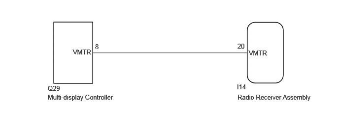
PROCEDURE
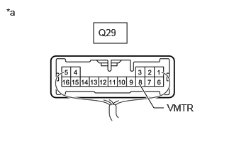
| *a | Component with harness connected (Multi-display Controller) |
Measure the voltage according to the value(s) in the table below.
- Standard Voltage:
-
Tester Connection Condition Specified Condition Click Location & Routing(Q29)Location & Routingewd_type=routing;type=c;code=Q29
Click Connector(Q29)Seat>Floor Wire>Multi-Display Controllerewd_type=component;type=c;code=Q29;pinno=8
Q29-8 (VMTR) - Body ground RSE playing →
Source changedHigher than 3.5 V
→ Below 1 V
- Result:
-
Proceed to OK NG
OK
Click hereGeneral>INTRODUCTION>HOW TO TROUBLESHOOT ECU CONTROLLED SYSTEMS>HOW TO PROCEED WITH TROUBLESHOOTING
NG
Disconnect the Q29 multi-display controller connector.
Disconnect the I14 radio receiver assembly connector.
Measure the resistance according to the value(s) in the table below.
- Standard Resistance:
-
Tester Connection Condition Specified Condition Click Location & Routing(Q29,I14)Location & Routingewd_type=routing;type=c,c;code=Q29,I14
Click Connector(Q29)Seat>Floor Wire>Multi-Display Controllerewd_type=component;type=c;code=Q29;pinno=8
Q29-8 (VMTR) - I14-20 (VMTR) Always Below 1 Ω Q29-8 (VMTR) - Body ground Always 10 kΩ or higher
- Result:
-
Proceed to OK NG
OK
NG
Disconnect the Q29 multi-display controller connector.
Measure the voltage according to the value(s) in the table below.
- Standard Voltage:
-
Tester Connection Condition Specified Condition Click Location & Routing(Q29)Location & Routingewd_type=routing;type=c;code=Q29
Click Connector(Q29)Seat>Floor Wire>Multi-Display Controllerewd_type=component;type=c;code=Q29;pinno=8
Q29-8 (VMTR) - Body ground RSE playing Higher than 3.5 V
- Result:
-
Proceed to OK NG
OK
NG
Click hereAudio / Visual / Telematics>AUDIO / VIDEO>RADIO RECEIVER (for Radio Receiver Type)>REMOVAL