HEATING / AIR CONDITIONING AIR CONDITIONING SYSTEM B14B287 Lost Communication with Front Panel LIN Missing Message
DESCRIPTION
The integration control and panel sub-assembly communicates with the air conditioning amplifier assembly via LIN communication.
| DTC No. | Detection Item | DTC Detection Condition | Trouble Area | Memory | DTC Output from | Priority |
|---|---|---|---|---|---|---|
| B14B287 | Lost Communication with Front Panel LIN Missing Message | Diagnosis Condition: Ignition switch ON Malfunction Status: Error or open in communication line between air conditioning amplifier assembly and air conditioning control assembly Detection Time: Continuously for 10 seconds or more |
·
Harness or connector
·
Air conditioning control assembly
·
Air conditioning control assembly |
Memorized | Air Conditioner | A |
| Vehicle Condition | |||
|---|---|---|---|
| Pattern 1 | Pattern 2 | ||
| Diagnosis Condition | Ignition switch ON | ○ | ○ |
| Malfunction Status | Error in communication line between air conditioning amplifier assembly and air conditioning control assembly | ○ | - |
| Open in communication line between air conditioning amplifier assembly and air conditioning control assembly | - | ○ | |
| Detection Time | Continuously for 10 seconds or more | Continuously for 10 seconds or more | |
| Trip Count | 1 trip | 1 trip | |
- HINT:
-
If the conditions of either of these patterns are detected, a DTC will be stored.
WIRING DIAGRAM
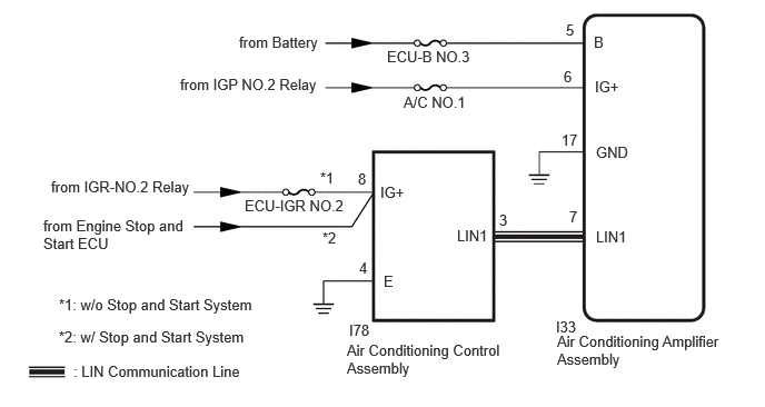
CAUTION / NOTICE / HINT
- NOTICE:
-
w/o Stop and Start System:
-
Inspect the fuses for circuits related to this system before performing the following procedure.
PROCEDURE
- Result:
-
Result Proceed to w/o Stop and Start System A w/ Stop and Start System B
A
B
Pre-procedure1
Disconnect the I78 air conditioning control assembly connector.
Procedure1
Measure the voltage according to the value(s) in the table below.
- Standard Voltage:
-
Tester Connection Switch Condition Specified Condition Click Location & Routing(I78)Location & Routingewd_type=routing;type=c;code=I78
I78-8 (IG+) - Body ground Ignition switch ON 11 to 14 V
- Result:
-
Proceed to OK NG
Post-procedure1
None
OK
NG
Pre-procedure1
Disconnect the I78 air conditioning control assembly connector.
Procedure1
Measure the resistance according to the value(s) in the table below.
- Standard Resistance:
-
Tester Connection Condition Specified Condition Click Location & Routing(I78)Location & Routingewd_type=routing;type=c;code=I78
I78-4 (E) - Body ground Always Below 1 Ω
- Result:
-
Proceed to OK NG
Post-procedure1
None
OK
NG
Pre-procedure1
Disconnect the I33 air conditioning amplifier assembly connector.
Disconnect the I78 air conditioning control assembly connector.
Procedure1
Measure the resistance according to the value(s) in the table below.
- Standard Resistance:
-
Tester Connection Condition Specified Condition Click Location & Routing(I33,I78)Location & Routingewd_type=routing;type=c,c;code=I33,I78
I33-7 (LIN1) - I78-3 (LIN1) Always Below 1 Ω I33-7 (LIN1) or I78-3 (LIN1) - Other terminals and body ground Always 10 kΩ or higher
- Result:
-
Proceed to OK NG
Post-procedure1
None
OK
NG
Using an oscilloscope, check the waveform.
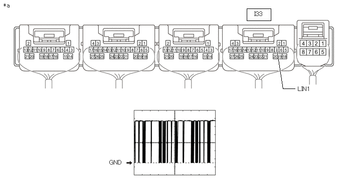
| *a | Component with harness connected (Air Conditioning Amplifier Assembly) |
- | - |
| Tester Connection | Tool Setting | Switch Condition |
|---|---|---|
Click Location & Routing(I33)Location & Routingewd_type=routing;type=c;code=I33 |
||
| I33-7 (LIN1) - Body ground | 2 V/DIV., 20 ms/DIV. | Ignition switch ON |
- OK:
-
The waveform displays properly.
- Result:
-
Proceed to OK NG
OK
NG
Click hereVehicle Interior>HEATING / AIR CONDITIONING>AIR CONDITIONING PANEL (for Front Side)>REMOVAL
Pre-procedure1
Disconnect the I78 air conditioning control assembly connector.
Procedure1
Measure the voltage according to the value(s) in the table below.
- Standard Voltage:
-
Tester Connection Condition Specified Condition Click Location & Routing(I78)Location & Routingewd_type=routing;type=c;code=I78
I78-8 (IG+) - Body ground Ignition switch ON 10.5 to 16 V
- Result:
-
Proceed to OK NG
Post-procedure1
None
OK
NG
Click hereEngine / Hybrid System>STOP AND START>STOP AND START SYSTEM>HOW TO PROCEED WITH TROUBLESHOOTING
Pre-procedure1
Disconnect the I78 air conditioning control assembly connector.
Procedure1
Measure the resistance according to the value(s) in the table below.
- Standard Resistance:
-
Tester Connection Switch Condition Specified Condition Click Location & Routing(I78)Location & Routingewd_type=routing;type=c;code=I78
I78-4 (E) - Body ground Always Below 1 Ω
- Result:
-
Proceed to OK NG
Post-procedure1
None
OK
NG
Pre-procedure1
Disconnect the I33 air conditioning amplifier assembly connector.
Disconnect the I78 air conditioning control assembly connector.
Procedure1
Measure the resistance according to the value(s) in the table below.
- Standard Resistance:
-
Tester Connection Condition Specified Condition Click Location & Routing(I33,I78)Location & Routingewd_type=routing;type=c,c;code=I33,I78
I33-7 (LIN1) - I78-3 (LIN1) Always Below 1 Ω I33-7 (LIN1) or I78-3 (LIN1) - Other terminals and body ground Always 10 kΩ or higher
- Result:
-
Proceed to OK NG
Post-procedure1
None
OK
NG
Using an oscilloscope, check the waveform.
| *a | Component with harness connected (Air Conditioning Amplifier Assembly) |
- | - |
| Tester Connection | Tool Setting | Switch Condition |
|---|---|---|
Click Location & Routing(I33)Location & Routingewd_type=routing;type=c;code=I33 |
||
| I33-7 (LIN1) - Body ground | 2 V/DIV., 20 ms/DIV. | Ignition switch ON |
- OK:
-
The waveform displays properly.
- Result:
-
Proceed to OK NG
OK
NG
Click hereVehicle Interior>HEATING / AIR CONDITIONING>AIR CONDITIONING PANEL (for Front Side)>REMOVAL