HEATING / AIR CONDITIONING AIR CONDITIONING PRESSURE SENSOR ON-VEHICLE INSPECTION
PROCEDURE

 88719A 1.INSPECT AIR CONDITIONING PRESSURE SENSOR
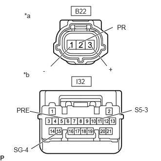
| *a | Front view of wire harness connector (to Air Conditioner Pressure Sensor) |
| *b | Front view of wire harness connector (to Air Conditioning Amplifier Assembly) |
Check the wire harness.
Disconnect the B22 air conditioning pressure sensor connector.
Disconnect the I32 air conditioning amplifier assembly connector.
Measure the resistance according to the value(s) in the table below.
- Standard Resistance:
-
Tester Connection Condition Specified Condition Click Location & Routing(B22,I32)Location & Routingewd_type=routing;type=c,c;code=B22,I32
B22-1 (-) - I32-15 (SG-4) Always Below 1 Ω B22-2 (PR) - I32-6 (PRE) Always Below 1 Ω B22-3 (+) - I32-11 (S5 -3) Always Below 1 Ω B22-1 (-) - Body ground Always 10 kΩ or higher I32-15 (SG-4) - Body ground Always 10 kΩ or higher B22-2 (PR) - Body ground Always 10 kΩ or higher I32-6 (PRE) - Body ground Always 10 kΩ or higher B22-3 (+) - Body ground Always 10 kΩ or higher I32-11 (S5 -3) - Body ground Always 10 kΩ or higher
If the resistance is not as specified, repair the wire harness.
Check the voltage.
Reconnect the I32 air conditioning amplifier assembly connector.
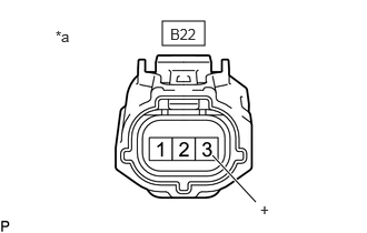
| *a | Front view of wire harness connector (to Air Conditioner Pressure Sensor) |
Measure the voltage according to the value(s) in the table below.
- Standard Voltage:
-
Tester Connection Condition Specified Condition Click Location & Routing(B22)Location & Routingewd_type=routing;type=c;code=B22
B22-3 (+) - Body ground Ignition switch ON 4.75 to 5.25 V
If the voltage is not as specified, repair the wire harness or replace air conditioning amplifier assembly.
Check the air conditioning pressure sensor.
Install a manifold gauge set.
Connect the B22 air conditioning pressure sensor connector.
Turn the ignition switch to ON.
Measure the voltage according to the value(s) in the table below.
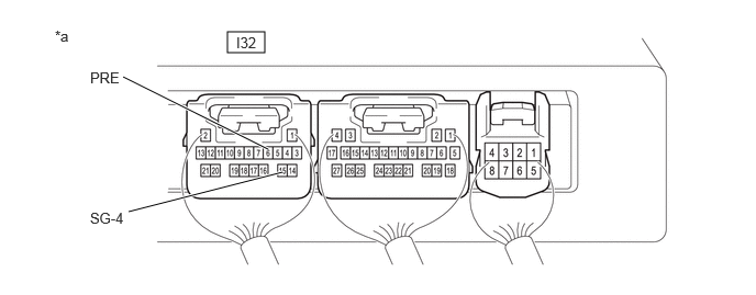
| *a | Component with harness connected (Air Conditioning Amplifier Assembly) |
- | - |
- Standard Voltage:
-
Tester Connection Condition Specified Condition *Value when sensor ignition source voltage is 5 V
Click Location & Routing(I32)Location & Routingewd_type=routing;type=c;code=I32
I32-6 (PRE) - I32-15 (SG-4) Refrigerant pressure: Normal pressure (less than 3025 kPaG (30.8 kgf/cm2, 439 psi) and more than 176 kPaG (1.8 kgf/cm2, 26 psi)) 0.62 to 4.73 V* I32-6 (PRE) - I32-15 (SG-4) Refrigerant pressure: Abnormal pressure (below 176 kPaG (1.8 kgf/cm2, 26 psi), or 3025 kPaG (30.8 kgf/cm2, 439 psi) or higher) Below 0.62 V, or 4.74 V or higher
If the result is not as specified, there may be a malfunction in the air conditioning pressure sensor.