INTERIOR PANELS / TRIM FRONT CONSOLE BOX(w/ Cool Box) INSPECTION
PROCEDURE

 88610S 1.INSPECT CONTROL SWITCH ASSEMBLY
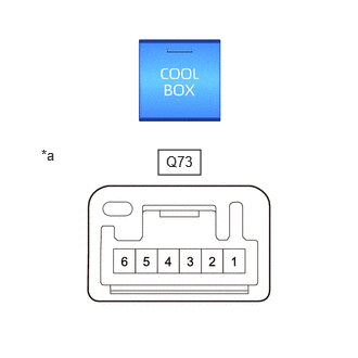
| *a | Component without harness connected (Control Switch Assembly) |
Check the switch.
Measure the resistance according to the value(s) in the table below.
- Standard Resistance:
-
Tester Connection Condition Specified Condition Click Location & Routing(Q73)Location & Routingewd_type=routing;type=c;code=Q73
Click Connector(Q73)Instrument Panel>Floor Wire / No. 1 Cooler Wiring Harness Sub-Assembly>Control Switch Assemblyewd_type=component;type=c;code=Q73;pinno=2,5
Q73-2 - Q73-5 Pushed (ON) Below 1 Ω Q73-2 - Q73-5 Not pushed (OFF) 10 kΩ or higher
If the result is not as specified, replace the control switch assembly.
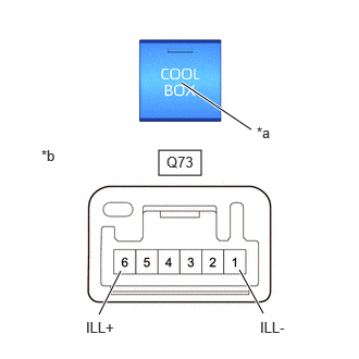
| *a | Illumination |
| *b | Component without harness connected (Control Switch Assembly) |
Check the illumination.
Apply battery voltage to the connector and check the illumination conditions.
- OK:
-
Tester Connection Specified Condition Click Location & Routing(Q73)Location & Routingewd_type=routing;type=c;code=Q73
Click Connector(Q73)Instrument Panel>Floor Wire / No. 1 Cooler Wiring Harness Sub-Assembly>Control Switch Assemblyewd_type=component;type=c;code=Q73;pinno=6,1
Battery positive (+) → Q73-6 (ILL+)
Battery negative (-) → Q73-1 (ILL-)Illumination illuminates
If the result is not as specified, replace the control switch assembly.
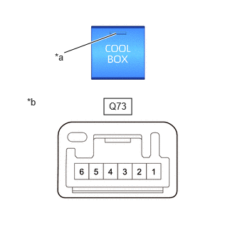
| *a | Indicator |
| *b | Component without harness connected (Control Switch Assembly) |
Check the indicator.
Apply battery voltage to the connector and check the indicator conditions.
- OK:
-
Tester Connection Specified Condition Click Location & Routing(Q73)Location & Routingewd_type=routing;type=c;code=Q73
Click Connector(Q73)Instrument Panel>Floor Wire / No. 1 Cooler Wiring Harness Sub-Assembly>Control Switch Assemblyewd_type=component;type=c;code=Q73;pinno=3,4
Battery positive (+) → Q73-3
Battery negative (-) → Q73-4Indicator illuminates
If the result is not as specified, replace the control switch assembly.
87103F 2.INSPECT COOL BOX BLOWER MOTOR WITH FAN SUB-ASSEMBLY
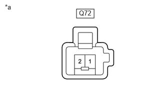
| *a | Component without harness connected (Cool Box Blower Motor With Fan Sub-assembly) |
Check the operation of the cool box blower motor with fan sub-assembly.
Apply battery voltage to the rear blower motor with fan sub-assembly terminals.
- OK:
-
Tester Connection Condition Specified Condition Click Location & Routing(Q72)Location & Routingewd_type=routing;type=c;code=Q72
Click Connector(Q72)Instrument Panel>Floor Wire / No. 1 Cooler Wiring Harness Sub-Assembly>Blower Motor (Cooling Box Assembly)ewd_type=component;type=c;code=Q72;pinno=1,2
Q72-1 - Auxiliary battery positive (+)
Q72-2 - Auxiliary battery negative (-)Always Operates smoothly
If the result is not as specified, replace the cool box blower motor with fan sub-assembly.
88625A 3.INSPECT NO. 2 COOLER THERMISTOR
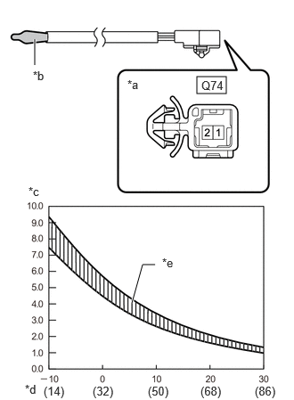
| *a | Component without harness connected (No. 2 Cooler Thermistor) |
| *b | Sensing Portion |
| *c | Resistance (kΩ) |
| *d | Temperature (°C (°F)) |
| *e | Allowable Range |
Measure the resistance according to the value(s) in the table below.
- Standard Resistance:
-
Tester Connection Condition Specified Condition Click Location & Routing(Q74)Location & Routingewd_type=routing;type=c;code=Q74
Click Connector(Q74)Instrument Panel>Floor Wire / No. 1 Cooler Wiring Harness Sub-Assembly>Thermistor (Cooling Box Assembly)ewd_type=component;type=c;code=Q74;pinno=1,2
Q74-1- Q74-2 -10°C (14°F) 7.40 to 9.20 kΩ Q74-1- Q74-2 -5°C (23°F) 5.65 to 7.00 kΩ Q74-1- Q74-2 0°C (32°F) 4.35 to 5.40 kΩ Q74-1- Q74-2 5°C (41°F) 3.40 to 4.20 kΩ Q74-1- Q74-2 10°C (50°F) 2.68 to 3.30 kΩ Q74-1- Q74-2 15°C (59°F) 2.10 to 2.60 kΩ Q74-1- Q74-2 20°C (68°F) 1.66 to 2.10 kΩ Q74-1- Q74-2 25°C (77°F) 1.32 to 1.66 kΩ Q74-1- Q74-2 30°C (86°F) 1.05 to 1.35 kΩ
- NOTICE:
-
·
Hold the sensor only by its connector. Touching the sensing portion may change the resistance value.
·When measuring, the sensor temperature must be the same as the ambient temperature.
- HINT:
-
As the temperature increases, the resistance decreases (see the graph).
If the result is not as specified, replace the No. 2 cooler thermistor.