RM38G0E _59 Vehicle Exterior _100866 WINCH _0468115 REMOTE CONTROL SWITCH G
WINCH REMOTE CONTROL SWITCH INSPECTION
PROCEDURE

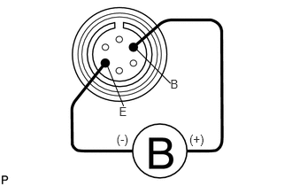
 1.INSPECT OVERHEAT TEMPERATURE INDICATOR
1.371,1.557 1.558,1.694 0.187,0.137 10 (-) 2.229,1.557 2.431,1.705 0.201,0.147 10 (+) 1.401,1.232 1.512,1.371 0.111,0.139 10 E 2.005,0.905 2.115,1.043 0.111,0.139 10 B 1.599,0.572 2.007,0.98 false 1.26,0.765 1.455,1.248 false
a.
Apply battery voltage and check operation of the remote control switch as shown in the table below.
- OK:
-
Measurement Condition Specified Condition Battery positive (+) → Terminal B
Battery negative (-) → Terminal EOverheat temperature indicator light illuminates and buzzer sounds
If the result is not as specified, replace the remote control switch.
38640 2.INSPECT WINCH CONTROL SWITCH ASSEMBLY
a.
2.817,0.294 2.944,0.440 0.127,0.147 10 A 2.817,0.839 2.948,0.985 0.130,0.147 10 B 2.817,1.179 2.946,1.325 0.128,0.147 10 C 0.497,1.727 0.639,1.887 0.142,0.161 10 D 0.497,1.179 0.614,1.321 0.117,0.142 10 E 0.497,0.839 0.616,0.990 0.119,0.151 10 F 2.08,0.923 2.795,0.923 false 2.082,1.26 2.797,1.26 false 0.652,0.925 1.366,0.925 false 0.654,1.261 1.369,1.261 false 1.785,0.744 2.567,0.377 2.567,0.377 2.771,0.377 false 1.659,1.45 0.877,1.817 0.877,1.817 0.673,1.817 false
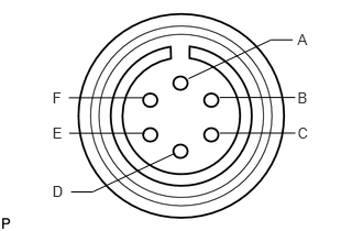
Check the resistance of the remote control switch assembly circuit.
i.
Apply battery voltage and measure the resistance according to the value(s) in the table below.
- Standard Resistance:
-
Tester Connection Battery Connection Specified Condition A - B Connect the positive (+) lead of the ohmmeter to terminal B and the negative (-) lead to terminal A. Below 1 Ω B - E Connect the positive (+) lead of the ohmmeter to terminal E and the negative (-) lead to terminal B. Below 1 Ω
If the result is not as specified, replace the remote control switch assembly.
ii.
Measure the resistance according to the value(s) in the table below.
- Standard Resistance:
-
Tester Connection Switch Condition Specified Condition B - C Not pushed Below 1 Ω B - D Pushed to IN Below 1 Ω B - F Pushed to OUT Below 1 Ω
If the result is not as specified, replace the remote control switch assembly.