RM38G0E _59 Vehicle Exterior _100866 WINCH _0468116 RELAY G
WINCH RELAY INSPECTION
PROCEDURE

 38630 1.INSPECT NO. 1 MAGNET SWITCH ASSEMBLY
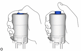
a.
Push in the plunger and release it. Check that it returns quickly to its original position.
b.
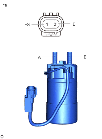
2.417,1.917 2.75,1.917 false 1.427,1.917 1.76,1.917 false 1.063,0.813 1.479,0.813 true 1.948,0.802 2.365,0.802 true 0.104,0.083 0.417,0.281 0.313,0.198 10 false *a 1.281,1.844 1.438,2.042 0.156,0.198 10 false A 2.823,1.833 3.094,2.021 0.271,0.188 10 false B 0.833,0.74 1.146,0.938 0.313,0.198 10 false +S 2.448,0.729 2.76,0.927 0.313,0.198 10 false E
| *a | Component without harness connected (No. 1 Magnet Switch Assembly) |
Measure the resistance according to the value(s) in the table below.
- Standard Resistance:
-
Tester Connection Condition Specified Condition A - B Battery voltage is not applied to terminals 1(+S) and 2(E) 10 kΩ or higher Battery voltage applied positive (+) lead to terminals 1(+S) and negative (-) lead to terminals 2(E) Below 1 Ω
If the result is not as specified, replace the No. 1 magnet switch assembly.