SEAT POWER SEAT SWITCH(for Rear No. 2 Seat) INSPECTION
PROCEDURE

 84923 1.INSPECT REAR POWER SEAT SWITCH (for LH Side)
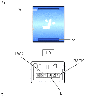
| *a | Component without harness connected (Rear Power Seat Switch) |
| *b | Forward Switch |
| *c | Backward Switch |
Measure the resistance according to the value(s) in the table below.
- Standard Resistance:
-
Tester Connection Switch Condition Specified Condition Click Location & Routing(U9)Location & Routingewd_type=routing;type=c;code=U9
Click Connector(U9)Body>No. 2 Room Wire>Rear Power Seat Switch LHewd_type=component;type=c;code=U9;pinno=4,3,1
U9-4 (FWD) - U9-3 (E) Forward switch pressed Below 1 Ω U9-1 (BACK) - U9-3 (E) Backward switch pressed
If the result is not as specified, replace the rear power seat switch.
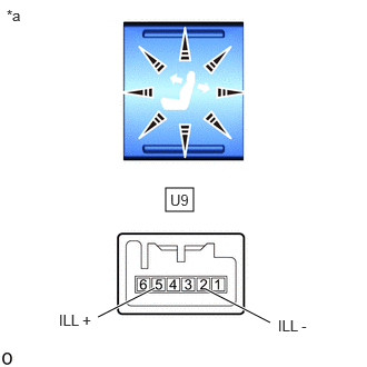
| *a | Component without harness connected (Rear Power Seat Switch) |
Apply battery voltage to the switch connector and check that the power seat switch illuminates.
- OK:
-
Tester Connection Specified Condition Click Location & Routing(U9)Location & Routingewd_type=routing;type=c;code=U9
Click Connector(U9)Body>No. 2 Room Wire>Rear Power Seat Switch LHewd_type=component;type=c;code=U9;pinno=5,2
U9-5 (ILL+) - battery positive (+)
U9-2 (ILL-) - battery negative (-)Illumination illuminates
If the result is not as specified, replace the rear power seat switch.
84923 2.INSPECT REAR POWER SEAT SWITCH (for RH Side)
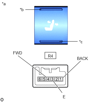
| *a | Component without harness connected (Rear Power Seat Switch) |
| *b | Forward Switch |
| *c | Backward Switch |
Measure the resistance according to the value(s) in the table below.
- Standard Resistance:
-
Tester Connection Switch Condition Specified Condition Click Location & Routing(R4)Location & Routingewd_type=routing;type=c;code=R4
Click Connector(R4)Body>Room Wire>Rear Power Seat Switch RHewd_type=component;type=c;code=R4;pinno=4,3,1
R4-4 (FWD) - R4-3 (E) Forward switch pressed Below 1 Ω R4-1 (BACK) - R4-3 (E) Backward switch pressed
If the result is not as specified, replace the rear power seat switch.
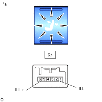
| *a | Component without harness connected (Rear Power Seat Switch) |
Apply battery voltage to the switch connector and check that the power seat switch illuminates.
- OK:
-
Tester Connection Specified Condition Click Location & Routing(R4)Location & Routingewd_type=routing;type=c;code=R4
Click Connector(R4)Body>Room Wire>Rear Power Seat Switch RHewd_type=component;type=c;code=R4;pinno=5,2
R4-5 (ILL+) - battery positive (+)
R4-2 (ILL-) - battery negative (-)Illumination illuminates
If the result is not as specified, replace the rear power seat switch.
84190A 3.INSPECT NO. 1 FOLD SEAT SWITCH ASSEMBLY
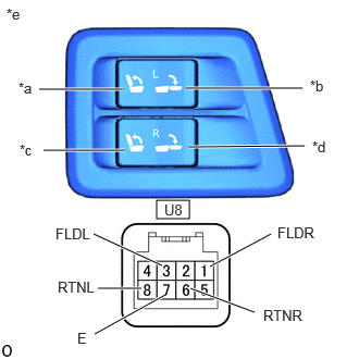
| *a | RETURN LH Switch |
| *b | FOLD LH Switch |
| *c | RETURN RH Switch |
| *d | FOLD RH Switch |
| *e | Component without harness connected (No. 1 Fold Seat Switch Assembly) |
Measure the resistance according to the value(s) in the table below.
- Standard Resistance:
-
Tester Connection Switch Condition Specified Condition Click Location & Routing(U8)Location & Routingewd_type=routing;type=c;code=U8
Click Connector(U8)Body>No. 2 Room Wire>Fold Seat Switch Assembly LHewd_type=component;type=c;code=U8;pinno=8,7,3,6,1
U8-8 (RTNL) - U8-7 (E) RETURN LH switch pressed Below 1 Ω U8-3 (FLDL) - U8-7 (E) FOLD LH switch pressed U8-6 (RTNR) - U8-7 (E) RETURN RH switch pressed U8-1 (FLDR) - U8-7 (E) FOLD RH switch pressed
If the result is not as specified, replace the No. 1 fold seat switch assembly.
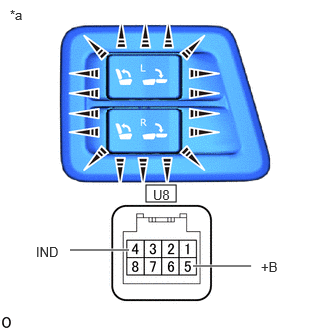
| *a | Component without harness connected (No. 1 Fold Seat Switch Assembly) |
Apply battery voltage to the switch connector and check that the fold seat switch illuminates.
- OK:
-
Tester Connection Specified Condition Click Location & Routing(U8)Location & Routingewd_type=routing;type=c;code=U8
Click Connector(U8)Body>No. 2 Room Wire>Fold Seat Switch Assembly LHewd_type=component;type=c;code=U8;pinno=5,4
U8-5 (+B) - battery positive (+)
U8-4 (IND) - battery negative (-)Illumination illuminates
If the result is not as specified, replace the No. 1 fold seat switch assembly.
84190B 4.INSPECT NO. 2 FOLD SEAT SWITCH ASSEMBLY
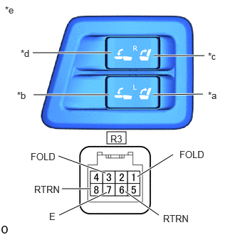
| *a | RETURN LH Switch |
| *b | FOLD LH Switch |
| *c | RETURN RH Switch |
| *d | FOLD RH Switch |
| *e | Component without harness connected (No. 2 Fold Seat Switch Assembly) |
Measure the resistance according to the value(s) in the table below.
- Standard Resistance:
-
Tester Connection Switch Condition Specified Condition Click Location & Routing(R3)Location & Routingewd_type=routing;type=c;code=R3
Click Connector(R3)Body>Room Wire>Fold Seat Switch Assembly RHewd_type=component;type=c;code=R3;pinno=8,7,3,6,1
R3-8 (RTRN) - R3-7 (E) RETURN LH switch pressed Below 1 Ω R3-3 (FOLD) - R3-7 (E) FOLD LH switch pressed R3-6 (RTRN) - R3-7 (E) RETURN RH switch pressed R3-1 (FOLD) - R3-7 (E) FOLD RH switch pressed
If the result is not as specified, replace the No. 2 fold seat switch assembly.
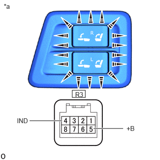
| *a | Component without harness connected (No. 2 Fold Seat Switch Assembly) |
Apply battery voltage to the switch connector and check that the fold seat switch illuminates.
- OK:
-
Tester Connection Specified Condition Click Location & Routing(R3)Location & Routingewd_type=routing;type=c;code=R3
Click Connector(R3)Body>Room Wire>Fold Seat Switch Assembly RHewd_type=component;type=c;code=R3;pinno=5,4
R3-5 (+B) - battery positive (+)
R3-4 (IND) - battery negative (-)Illumination illuminates
If the result is not as specified, replace the No. 2 fold seat switch assembly.
84190 5.INSPECT FOLD SEAT SWITCH ASSEMBLY
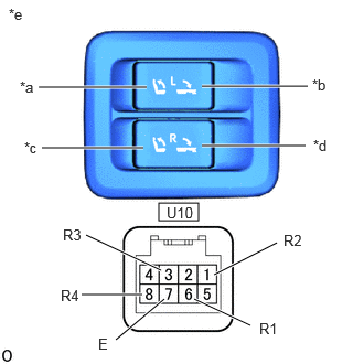
| *a | RETURN LH Switch |
| *b | FOLD LH Switch |
| *c | RETURN RH Switch |
| *d | FOLD RH Switch |
| *e | Component without harness connected (Fold Seat Switch Assembly) |
Measure the resistance according to the value(s) in the table below.
- Standard Resistance:
-
Tester Connection Switch Condition Specified Condition Click Location & Routing(U10)Location & Routingewd_type=routing;type=c;code=U10
Click Connector(U10)Body>No. 2 Room Wire>Fold Seat Switch Assemblyewd_type=component;type=c;code=U10;pinno=8,7,3,6,1
U10-8 (R4) - U10-7 (E) RETURN LH switch pressed Below 1 Ω U10-3 (R3) - U10-7 (E) FOLD LH switch pressed U10-6 (R1) - U10-7 (E) RETURN RH switch pressed U10-1 (R2) - U10-7 (E) FOLD RH switch pressed
If the result is not as specified, replace the fold seat switch assembly.
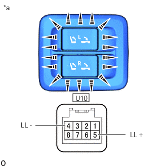
| *a | Component without harness connected (Fold Seat Switch Assembly) |
Apply battery voltage to the switch connector and check that the fold seat switch illuminates.
- OK:
-
Tester Connection Specified Condition Click Location & Routing(U10)Location & Routingewd_type=routing;type=c;code=U10
Click Connector(U10)Body>No. 2 Room Wire>Fold Seat Switch Assemblyewd_type=component;type=c;code=U10;pinno=5,4
U10-5 (LL+) - battery positive (+)
U10-4 (LL-) - battery negative (-)Illumination illuminates
If the result is not as specified, replace the fold seat switch assembly.