RM38G0E _56 Audio / Visual / Telematics _100607 NAVIGATION / MULTI INFO DISPLAY _0467505 TOYOTA MULTI OPERATION TOUCH SYSTEM U
NAVIGATION / MULTI INFO DISPLAY TOYOTA MULTI OPERATION TOUCH SYSTEM TERMINALS OF ECU
- HINT:
-
Check from the rear of the connector while it is connected to the components.
INTEGRATION CONTROL SUB-ASSEMBLY
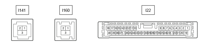
4.885,0.188 5.323,0.5 0.438,0.313 2.052,0.188 2.49,0.5 0.438,0.313 0.552,0.188 0.99,0.5 0.438,0.313 5.01,0.271 5.469,0.469 0.458,0.198 10 false I22 0.625,0.271 1.24,0.469 0.615,0.198 10 false I141 2.135,0.271 2.75,0.469 0.615,0.198 10 false I160
| Terminal No. (Symbol) | Terminal Description | Condition | Specified Condition |
|---|---|---|---|
|
*1: w/ Stop and Start System *2: w/o Stop and Start System |
|||
| I22-1 (B) - I22-20 (GND) | Power source (+B) | Always | 10.5 to 16 V*1 |
| 11 to 14 V*2 | |||
| I22-3 (ACC) - I22-20 (GND) | Power source (ACC) | Ignition switch off | Below 1 V |
| Ignition switch ACC | 10.5 to 16 V*1 | ||
| 11 to 14 V*2 | |||
| I22-4 (IG+) - I22-20 (GND) | Power source (IG) | Ignition switch off | Below 1 V |
| Ignition switch ON | 10.5 to 16 V*1 | ||
| 11 to 14 V*2 | |||
| I22-5 (ILL+) - I22-20 (GND) | Illumination signal | Ignition switch ON Light control switch AUTO, expose the automatic light control sensor to a light |
Below 1 V |
| Ignition switch ON Light control switch in tail or head position |
11 to 14 V | ||
| I22-17 (VMTT) - I22-20 (GND) | Visual mute signal | Ignition switch ACC Screen display changing |
3.5 V or higher → Below 1 V → 3.5 V or higher |
| I22-18 (TX+) - I22-20 (GND) | AVC-LAN communication signal | - | - |
| I22-20 (GND) - Body ground | Ground | Always | Below 1 Ω |
| I22-31 (CANN) | CAN communication signal | - | - |
| I22-32 (CANP) | CAN communication signal | - | - |
| I22-35 (TX1-) | AVC-LAN communication signal | - | - |
| I22-36 (TX1+) | AVC-LAN communication signal | - | - |
| I22-39 (VMTI) - I22-20 (GND) | Visual mute signal | Ignition switch ACC Screen display changing |
3.5 V or higher → Below 1 V → 3.5 V or higher |
| I22-40 (TX-) - I22-20 (GND) | AVC-LAN communication signal | - | - |
| I141-1 (GV+) | Video signal (Digital) | - | - |
| I141-2 (GV-) | Video signal (Digital) | - | - |
| I141-3 (GVG) - Body ground | Shield ground | Always | Below 1 Ω |
| I160-1 (GV2-) | Video signal (Digital) | - | - |
| I160-2 (GV2+) | Video signal (Digital) | - | - |
| I160-3 (GVG2) - Body ground | Shield ground | Always | Below 1 Ω |
MULTI-DISPLAY ASSEMBLY
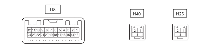
1.521,0.167 2.031,0.458 0.51,0.292 4.385,0.313 4.833,0.583 0.448,0.271 5.833,0.313 6.281,0.583 0.448,0.271 1.677,0.24 2.135,0.438 0.458,0.198 10 false I18 4.469,0.385 5.083,0.583 0.615,0.198 10 false I140 5.917,0.385 6.531,0.583 0.615,0.198 10 false I125
| Terminal No. (Symbol) | Terminal Description | Condition | Specified Condition |
|---|---|---|---|
|
*1: w/ Stop and Start System *2: w/o Stop and Start System |
|||
| I18-2 (ILL) - I18-13 (GND1) | Illumination signal | Ignition switch ON Light control switch AUTO, expose the automatic light control sensor to a light |
Below 1 V |
| Ignition switch ON Light control switch in tail or head position |
11 to 14 V | ||
| I18-7 (TX+) | AVC-LAN communication signal | - | - |
| I18-11 (VMTI) - I18-13 (GND1) | Visual mute signal | When image on display switches | 3.5 V or higher → Below 1 V → 3.5 V or higher |
| I18-12 (B) - I18-13 (GND1) | Power source (+B) | Always | 10.5 to 16 V*1 |
| 11 to 14 V*2 | |||
| I18-13 (GND1) - Body ground | Ground | Always | Below 1 Ω |
| I18-19 (TX-) | AVC-LAN communication signal | - | - |
| I18-24 (ACC) - I18-13 (GND1) | Power source (ACC) | Ignition switch off | Below 1 V |
| Ignition switch ACC | 10.5 to 16 V*1 | ||
| 11 to 14 V*2 | |||
| I140-1 (GV*+) | Video signal (Digital) | - | - |
| I140-2 (GV*-) | Video signal (Digital) | - | - |
| I140-3 (GVG*) | Shield ground | - | - |
| I125-1 (GVO+) | Video signal (Digital) | - | - |
| I125-2 (GVO-) | Video signal (Digital) | - | - |
| I125-3 (GVG1) | Shield ground | - | - |
RADIO RECEIVER ASSEMBLY
w/ Navigation System: Click hereAudio / Visual / Telematics>NAVIGATION / MULTI INFO DISPLAY>NAVIGATION SYSTEM>TERMINALS OF ECU
w/o Navigation System: Click hereAudio / Visual / Telematics>AUDIO / VIDEO>AUDIO AND VISUAL SYSTEM (for Radio and Display Type, for 12.3 Inch Display)>TERMINALS OF ECU